
Anti-ligature lever

a technology of levers and ligatures, applied in the direction of door/window fittings, building locks, construction, etc., can solve the problems of increasing the risk of suicide by those inside, and it is not possible to monitor continuously all patients and inmates

Active Publication Date: 2020-04-02
SARGENT MANUFACTURING CO INC
View PDF0 Cites 0 Cited by
  • Summary
  • Abstract
  • Description
  • Claims
  • Application Information

AI Technical Summary

Benefits of technology

The present invention provides an anti-ligature lock with a door handle that does not allow the end of a ligature to be secured to the handle. The lock includes a connector between the lock hub and the lock handle that is rotatable about an axis. The connector has a female portion with an opening and a male portion with projections that can engage with the female portion to secure the lock. The lock handle can partially rotate in either direction without causing the hub to rotate, and the projections on the male portion will engage with the female portion to drive engagement between the two. The invention also provides a lock connector that includes a cylindrical base portion, a female portion with an opening, and a male portion with projections that can engage with a door lock hub for sliding a door latch from a door securing position.

Problems solved by technology

Under such circumstances, there is an increased risk of suicide by those within.
Because it is not possible for all patients and inmates to be continuously monitored, public buildings of the aforementioned type are increasingly being provided with specially designed anti-ligature locks and door handles.

Method used


Image

  • Anti-ligature lever
  • Anti-ligature lever
  • Anti-ligature lever

Examples


Embodiment Construction

)

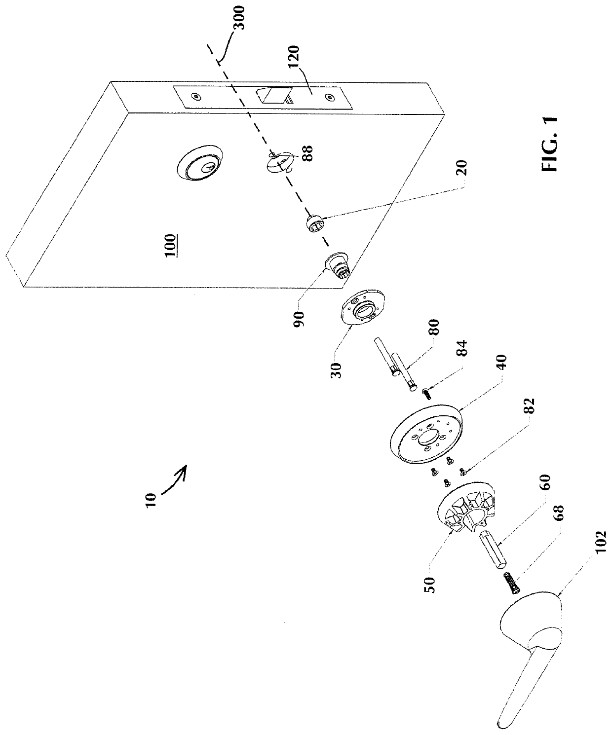
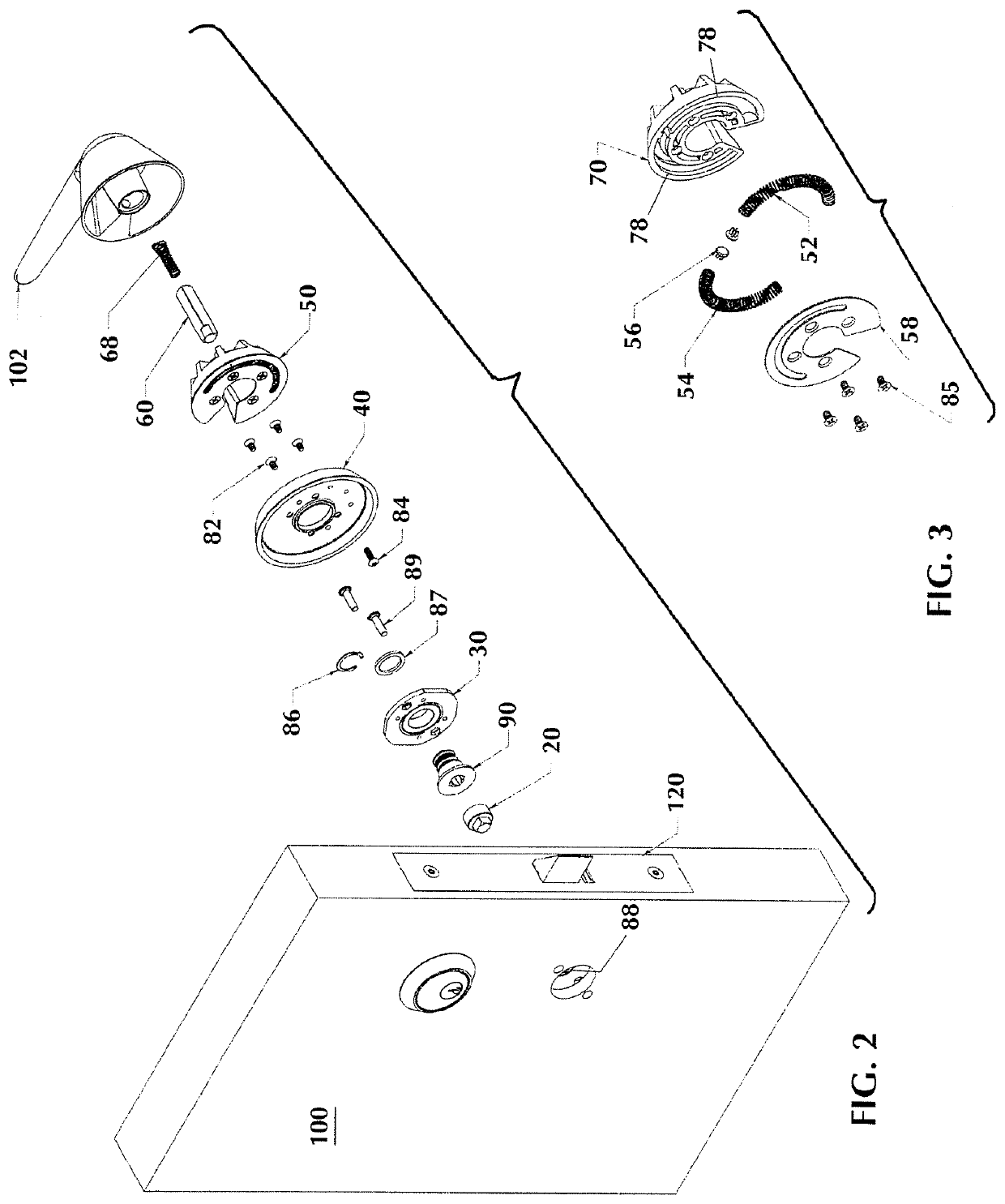
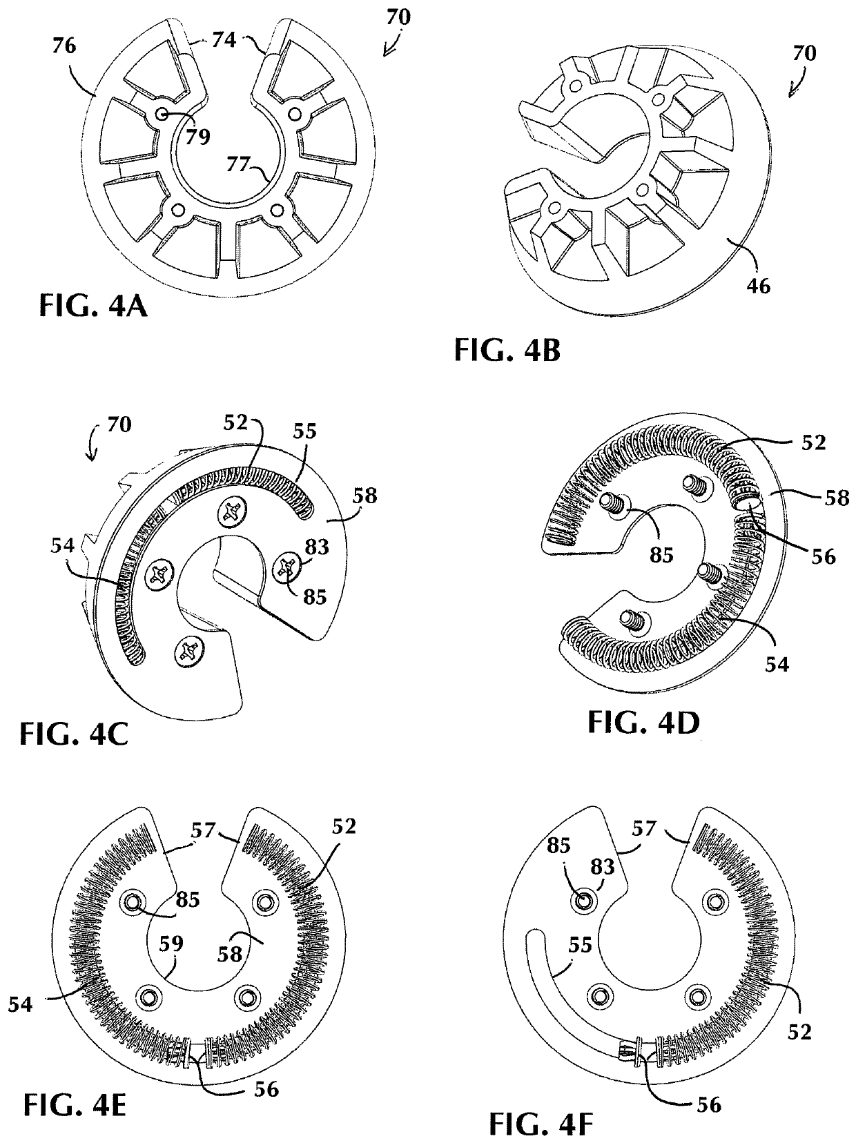
[0061]In describing the preferred embodiment of the present invention, reference will be made herein to FIGS. 1-23 of the drawings in which like numerals refer to like features of the invention.

[0062]FIGS. 1 and 2 show the anti-ligature lever 10 attachable to a door 100 having a mortise lock or other locking mechanism 120. The locking mechanism 120 includes a locking hub 88 to which an adapter bushing 20 of the anti-ligature lever assembly 10 may be engaged. The locking mechanism hub 88 is rotatable about an axis 300 to retract a latch or deadbolt between locked and unlocked positions. The anti-ligature lever 10 includes a lock handle 102 rotatable by a user about the axis 300 and operatively connected to the hub 88 to rotate the hub 88 and retract a latch or deadbolt between locked and unlocked positions.

[0063]The anti-ligature lever 10 includes a bushing 90 for securing a spindle 60 about the axis 300. The handle 102 engages the spindle 60 and an anti-ligature cartridge 50 whereb...


PUM


Abstract

An anti-ligature lock having a locking mechanism for retracting a latch between a locked and an unlocked position. The anti-ligature lock includes a lock handle rotatable about the axis and operatively connected to a lock mechanism hub to rotate the hub and retract the latch between the locked and the unlocked positions. The anti-ligature lock includes a connector between the hub and the lock handle and rotatable about the axis, the connector having a female portion having an opening with walls elongated in a direction normal to the axis and a male portion having projections extending in opposite directions normal to the axis, the male portion extending within the female portion opening and having a neutral position wherein one of the male or female portion may be partially rotated in either direction about the axis with respect to the other of the male or female portion without the male portion projections contacting the female portion opening walls.

Description

BACKGROUND OF THE INVENTION1. Field of the Invention[0001]The present invention relates generally to anti-ligature lock mechanisms, escutcheons and door handles designed to prevent suicide by preventing the securing of a ligature to the door handle or the lock mechanism.2. Description of Related Art[0002]Buildings such as hospitals, mental health facilities, prisons, detention centers and the like are locations where patients, inmates and detainees are subject to stress and high levels of emotion. Under such circumstances, there is an increased risk of suicide by those within.[0003]A common type of attempted suicide or self-harm is by hanging or strangulation by attaching a ligature, such as clothing or a belt to a conventional door knob or lever handle. Because it is not possible for all patients and inmates to be continuously monitored, public buildings of the aforementioned type are increasingly being provided with specially designed anti-ligature locks and door handles. The use ...

Claims


Application Information

Patent Timeline
Patent Type & Authority Applications(United States)
IPC IPC(8): E05B3/06E05B15/00
CPCE05B15/0033E05Y2900/132E05B3/065Y10T292/93
Inventor RILEY, DANIEL W.SANGSTER, JR., RICHARD D.
Owner SARGENT MANUFACTURING CO INC
Learn More