Piezoelectric ink jet head

a technology of piezoelectric elements and jet heads, which is applied in printing and other directions, can solve the problem of becoming difficult to dispose of independent piezoelectric elements individually in correspondence to pressure chambers

Active Publication Date: 2006-09-26
KYOCERA CORP
View PDF9 Cites 0 Cited by
  • Summary
  • Abstract
  • Description
  • Claims
  • Application Information

AI Technical Summary

Benefits of technology

[0020]An object of the present invention is to provide a piezoelectric ink jet head that does not allow the dot size and / or dot shape to change regardless of the dot pattern of the picture to be formed, since the state of driving the individual drive region or the individual piezoelectric elements is not affected by the state of driving the plurality of other drive regions or the piezoelectric elements.

Problems solved by technology

When resolution of the piezoelectric ink jet head becomes higher and the number of nozzles increases, however, it becomes difficult to dispose the independent piezoelectric elements individually in correspondence to the pressure chambers.
In case adjacent pressure chambers are disposed too close to each other, however, there arises such a problem that, when the piezoelectric element (drive region in the case of common element type) that corresponds to a particular one of the pressure chambers is driven, the piezoelectric element (or the drive region) corresponding to the adjacent pressure chambers that surround the particular pressure chamber are subject to the influence of driving of the piezoelectric element.
This problem is conspicuous particularly in the piezoelectric ink jet head of common element type.

Method used


Image

  • Piezoelectric ink jet head
  • Piezoelectric ink jet head
  • Piezoelectric ink jet head

Examples


example

Example 1

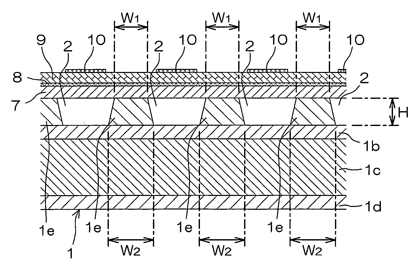
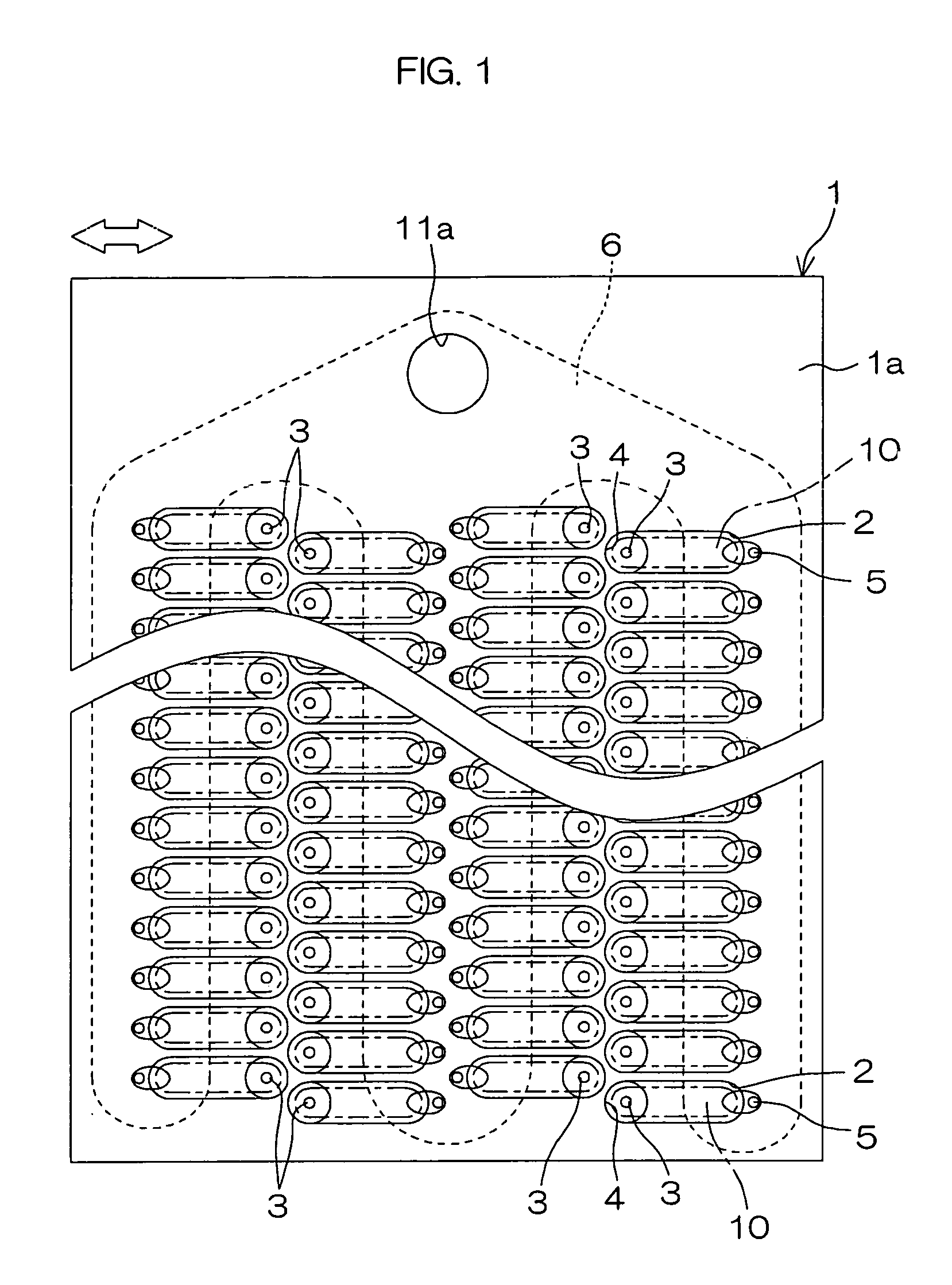
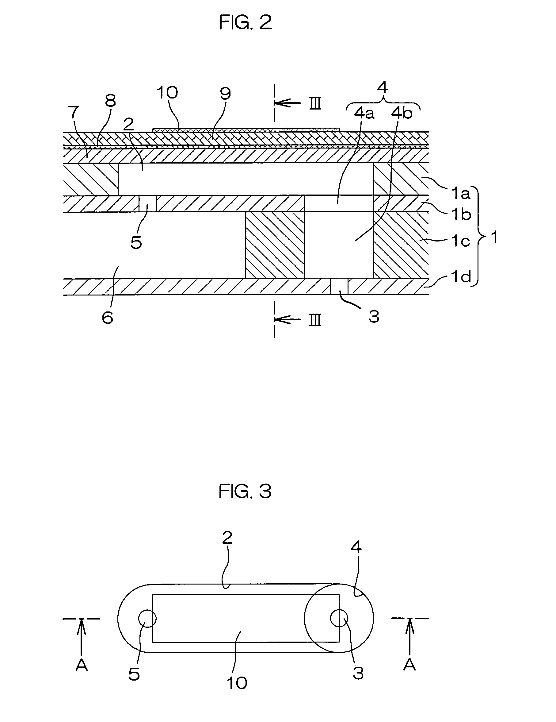
[0079]A piezoelectric ink jet head having the structure shown in FIG. 1 through FIG. 4 was fabricated with the pressure chamber 2 having area of 0.2 mm2 and measuring 200 μm in width and 80 μm in depth, the nozzle 3 measuring 25 μm in diameter and 30 μm in length, the nozzle passage 4 measuring 200 μm in diameter and 800 μm in length, the feed port 5 measuring 25 μm in diameter and 30 μm in length, and the partition walls 1e that separate the pressure chambers 2 having the width W1 of 82 μm and the width W2 of 82 μm. The height H of the partition wall 1e was 80 μm, the same as the depth of the pressure chamber 2.

Example 2

[0080]A piezoelectric ink jet head having the structure shown FIG. 1 through FIG. 3 and FIG. 5 was fabricated with the pressure chamber 2 having area of 0.2 mm2 at the opening of the recess and measuring 200 μm in width at the opening of the recess and 80 μm in depth, the nozzle 3 measuring 25 μm in diameter and 30 μm in length, the nozzle passage 4 measuri...


PUM


Abstract

The present invention is directed to a piezoelectric ink jet head wherein the partition walls that separate the adjacent recesses that make the pressure chambers are formed to have such a cross sectional shape as the width W1 in the planar direction at the upper end on the side of the substrate where the drive section is formed and height H in the direction of substrate thickness satisfy the expression (1):
W1≧H  (1)
while the width W1 and W2 of the lower end at the bottom of the recess of the substrate in the planar direction satisfy the expression (2):
W1≦W2  (2)
in order to prevent the dot size and dot shape of the picture to be formed from varying as the state of driving the individual drive regions or the state of driving the individual piezoelectric elements are influenced by the state of driving the other plurality of drive regions or the state of driving the individual piezoelectric elements that surround the former.

Description

[0001]This application is based on application No. 2003-146834 filed with the Japanese Patent Office, the content of which is incorporated hereinto by reference.TECHNICAL FIELD[0002]The present invention relates to a piezoelectric ink jet head and, more particularly, to a piezoelectric ink jet head that can be preferably used in printer, copier, facsimile, and a composite machine which combines some of the former.BACKGROUND OF THE INVENTION[0003]For a piezoelectric ink jet head that uses the electrostrictive effect of a piezoelectric element as the drive power source and is employed in an on-demand type ink jet printer, one having such a constitution is widely employed that comprises a plurality of pressure chambers to be filled with an ink disposed on one side of a plate-shaped substrate along the surface, with a nozzle for discharging the ink provided to communicate with each of the pressure chambers and a drive section including the piezoelectric element provided for each of the ...

Claims


Application Information

Patent Timeline
Patent Type & Authority Patents(United States)
IPC IPC(8): B41J2/045B41J2/14
CPCB41J2/14233B41J2002/14266B41J2/045B41J2/1404
Inventor SATAKE, KENICHIYOSHIMURA, KENICHI
Owner KYOCERA CORP
Why Eureka
Try Eureka