Power supply switching circuit and electronic device

a switching circuit and power supply technology, applied in electronic switching, emergency power supply arrangements, pulse techniques, etc., can solve the problems of short-circuit current flow between input terminals of a plurality of power supply potentials, risk of pmos transistor breakdown from b>17/b> to b>19/b>, and battery breakdown

Active Publication Date: 2017-09-28
SEIKO EPSON CORP
View PDF0 Cites 1 Cited by
  • Summary
  • Abstract
  • Description
  • Claims
  • Application Information

AI Technical Summary

Benefits of technology

[0009]In view of the above, one advantage of some aspects of the invention is to provide a power supply switching circuit that, even when selecting one power supply potential from among a plurality of power supply potentials, does not allow a short-circuit current to flow irrespective of the magnitude relation of the power supply potentials. Another advantage of some aspects of the invention is to enable one power supply potential to be selected in such a power supply switching circuit, according to the magnitudes of the power supply potentials that are supplied. A further advantage of some aspects of the invention is to provide an electronic device or the like that uses such a power supply switching circuit.

Problems solved by technology

In such a power supply switching circuit, there is a problem in that, when selecting one power supply potential from among the plurality of power supply potentials, a short-circuit current flows between input terminals of the plurality of power supply potentials.
As a result, there is a risk that breakdown of the PMOS transistors 17 to 19 will occur due to the short-circuit current.
Also, in the case where a battery is connected to the input terminal T1 or T2, there is a risk that breakdown of the battery will occur due to over-current, or that, in the case where a power supply circuit is connected to the input terminal T1 or T2, the output voltage of the power supply circuit will rise or fall.
As a result, a power supply switching circuit can be provided that, even when selecting one power supply potential from among a plurality of power supply potentials, does not allow a short-circuit current to flow irrespective of the magnitude relation of the power supply potentials.

Method used


Image

  • Power supply switching circuit and electronic device
  • Power supply switching circuit and electronic device
  • Power supply switching circuit and electronic device

Examples


first application example

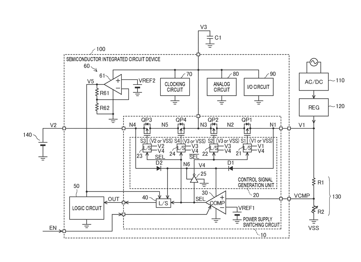
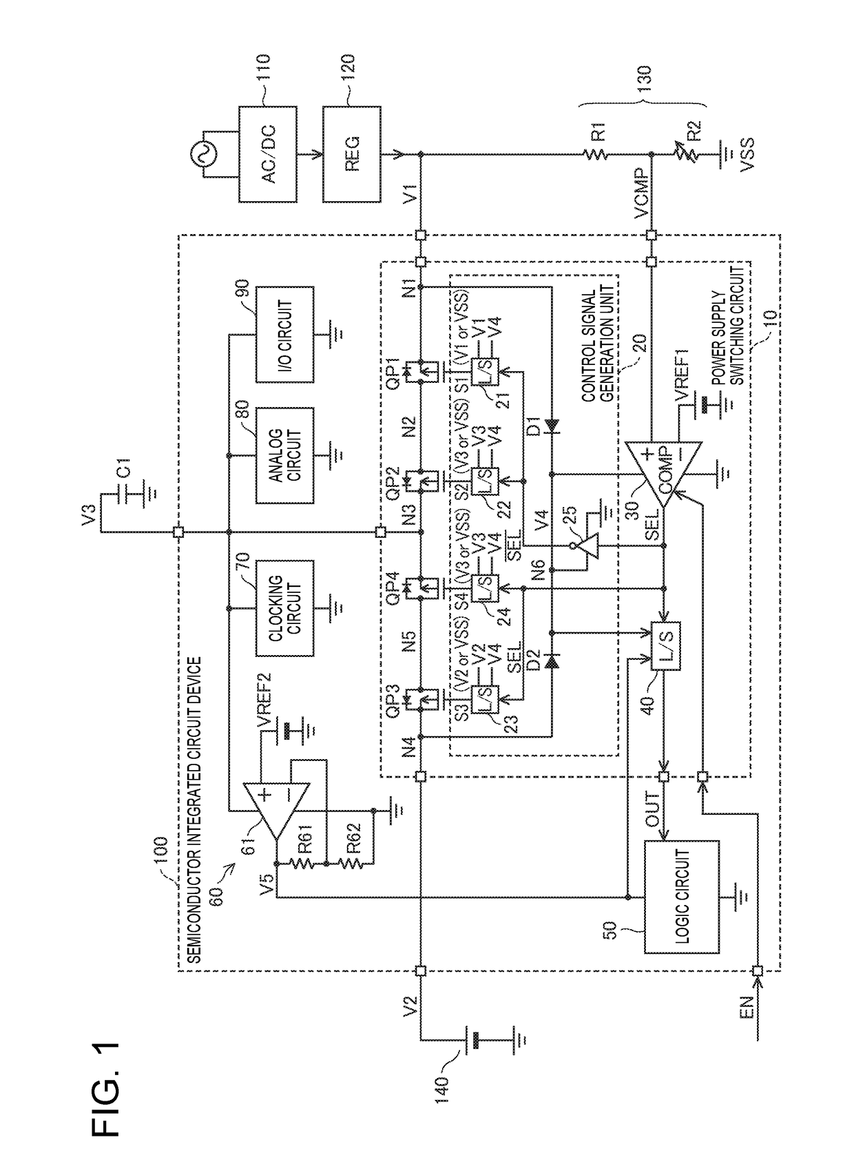
[0058]For example, when AC power supply voltage is no longer supplied at the time of the electronic device shown in FIG. 1 being transported, the AC / DC converter 110 and the regulator 120 stop operating, and the first power supply potential V1 falls to the reference potential VSS. Because the comparison voltage VCMP also falls to the reference potential VSS, the power supply selection signal SEL that is generated by the comparison unit 30 will be at a low level, and the power supply switching circuit 10 thereby selects the second power supply potential V2 that is supplied from the battery 140.

[0059]Even when the electronic device is operating using power supply from the battery 140, the clocking circuit 70 continues the clocking operation and continues to generate a clocking signal representing the current time. On the other hand, the logic circuit 50 stops operation in accordance with the power supply selection signal OUT that is generated when the comparison voltage VCMP is lower ...

second application example

[0061]There are also cases where the battery 140 is not necessary once the electronic device shown in FIG. 1 is installed. In such a case, the comparison unit 30 may stop the comparison operation and fix the level of the power supply selection signal SEL.

[0062]FIG. 4 is a circuit diagram showing an exemplary configuration of the comparison unit shown in FIG. 1. As shown in FIG. 4, the comparison unit 30 includes a resistor R30 and N-channel MOS transistors QN31 to QN34. Here, the transistors QN31 and QN32 constitute a differential pair. Also, the transistor QN34 constitutes a switch circuit that stops the comparison operation in accordance with the settings and fixes the level of the power supply selection signal SEL.

[0063]The transistor QN31 has a drain connected to the node N6 to which the internal power supply potential V4 is supplied, and a gate to which the comparison voltage VCMP is applied. The transistor QN32 has a drain connected to the node N6 via the resistor R30, and a g...


PUM


Abstract

A power supply switching circuit that selects one power supply potential from among a plurality of power supply potentials. This power supply switching circuit is provided with a transistor QP1 that is connected between an input node N1 and node N2 and has a back gate connected to node N1, a transistor QP2 that is connected between node N2 and output node N3 and has a back gate connected to node N3, a transistor QP3 that is connected between input node N4 and node N5 and has a back gate connected to node N4, a transistor QP4 that is connected between the node N5 and N3 and has a back gate connected to node N3, and a control signal generation unit that sets a group of transistors QP1 and QP2 and a group of transistors QP3 and QP4 to a conduction state and sets the other to a non-conduction state.

Description

BACKGROUND[0001]1. Technical Field[0002]The present invention relates to a power supply switching circuit that selects and outputs one power supply potential from among a plurality of power supply potentials. Furthermore, the invention relates to an electronic device or the like that uses such a power supply switching circuit.[0003]2. Related Art[0004]In electronic devices capable of receiving supply of power from a plurality of power supplies, a power supply switching circuit that selects and outputs one power supply potential from among a plurality of power supply potentials is used. In such a power supply switching circuit, there is a problem in that, when selecting one power supply potential from among the plurality of power supply potentials, a short-circuit current flows between input terminals of the plurality of power supply potentials.[0005]As a related technology, in FIG. 1 of JP-A-2012-191705, a power supply switching circuit that selects one of an input power supply volt...

Claims


Application Information

Patent Timeline
Patent Type & Authority Applications(United States)
IPC IPC(8): H03K17/687
CPCH03K17/6871H03K2217/0081H03K2217/0018H01L27/0207H01L27/0251H02J9/061H02J9/068H03K17/693
Inventor NOMIZO, HIROAKIKIYA, HIROSHIOIKAWA, NOBUYUKI
Owner SEIKO EPSON CORP
Why Eureka
Try Eureka