Microfluidic Device for Controlling the Geometry of Living Bodies

a microfluidic device and living body technology, applied in the field of microfluidic devices and processes, can solve the problems of difficult to keep knowledge of the physical connectivity of individual neurons, difficult to experiment at the cellular level, and in a dense 3d array

Active Publication Date: 2019-02-21
INSTITUT CURIE +2
View PDF3 Cites 0 Cited by
  • Summary
  • Abstract
  • Description
  • Claims
  • Application Information

AI Technical Summary

Benefits of technology

[0103]This design of the present invention allows the living bodies cultivated in the emitting chamber to be guided to the receiving chamber but does not allow the living bodies cultivated in the receiving chamber to be guided to the emitting chamber.

Problems solved by technology

The anatomical structures are intact but experimentation at the cellular level is severely restricted.
In this case, high resolution imaging and mechanical or chemical addressing are easier than in whole animals, but the lifetime of such cultures is short, and it is very difficult to keep knowledge of the physical connectivity of individual neurons, in a dense 3D array.
Also, in order to perform high resolution imaging, and feed correctly a living tissue disconnected from its natural vascular system, very thin slices must be made, so the real 3D architecture is strongly perturbed, and many neuronal connections are lost.
In these systems, however, cell development and connection is spatially random, making these systems very different from real ones in terms of cell-cell transactions and functionality.
However, this device still presents many limitations.
First, it makes it possible to separate the cellular compartments, but, if two populations are seeded in first and second chamber, it does not allow control of the direction of the connection of axons, thus making the connection not physiological.
First, the fabrication is delicate and leads to some irreproducibility.
Second, said narrow channels can be easily clogged by axons themselves, leading to irreproducibility and variations of fluidic connection during cell culture.
Said confinement adds flexibility to the design of neuronal arrays, but it requires complex chips with integrated electrodes, and complex control electronics.
For instance, many fabrication techniques have a limited resolution, so angles with a radius of gyration smaller than said resolution, or smaller than said resolution multiplied by some numerical factor, cannot be made.

Method used


Image

  • Microfluidic Device for Controlling the Geometry of Living Bodies
  • Microfluidic Device for Controlling the Geometry of Living Bodies
  • Microfluidic Device for Controlling the Geometry of Living Bodies

Examples


example 1

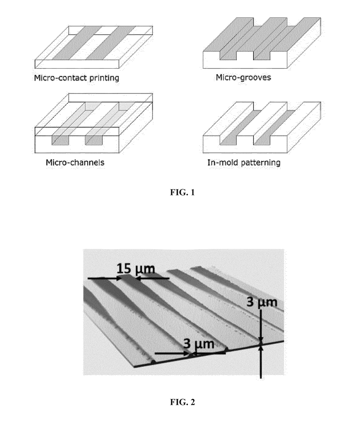
[0227]Examples of different types of guiding cues, as shown in FIG. 1, and of methods of prior art for the preparation of guiding patterns of the of the chemical type (surface treatment), of the physical type (microgrooves, microchannels), or of a type combining physical and chemical guiding cues (in mold patterning). The grey surfaces are FIG. 1 represent accessible areas while the white surfaces are inaccessible / repellent areas.

[0228]Creation of surface based guiding patterns (FIG. 1a) can be performed e.g. by microcontact printing, as in Offenhäusser A, et al. Soft Matter. 2007; 3:290-8. Microgrooves or microchannels (FIG. 1b, 1c) can be prepared e.g. by conventional techniques of soft lithography, by molding a polymer such as silicone (PDMS) upon a master, as described e.g. in Park J, et al. J Neurosci Methods. 2014; 221:166-74. The hybrid in mold patterning technique (FIG. 1d), finally, can be performed as described e.g. in Zhang J, et al. Biomaterials. 2006; 27:5734-9.

example 2

[0229]Example of designs of guiding patterns of prior art.

[0230]The guiding patterns presented in the following examples can refer indifferently to different patterning methods of prior art, as presented in FIG. 1, including guiding patterns of chemical nature (surface treatment), physical nature (microgrooves, microchannels), or of a combination of physical and chemical guiding cues (in-mold patterning). Various designs were presented e.g. in WO 2010040920 to Peyrin (FIG. 2A). among those, funnel shaped microchannels, such as represented in FIG. 2B, were used to produce directional filtering of axonal growth, using the higher probability of entry of the cell bodies (in particular, axons) into the wider entrance (here 15 μm wide) compared to the one for the narrower entrance (only 3 μm wide). However, making such tapered channels requires high resolution, hence costly microfabrication means, and the narrowing of the tracks in some embodiments can have harmful effects on axons or oth...

example 3

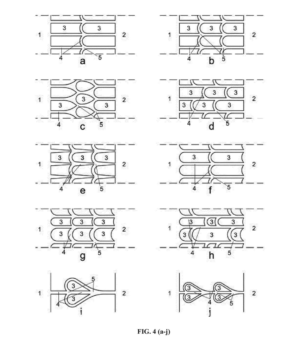
[0231]Examples of designs of devices of the invention.

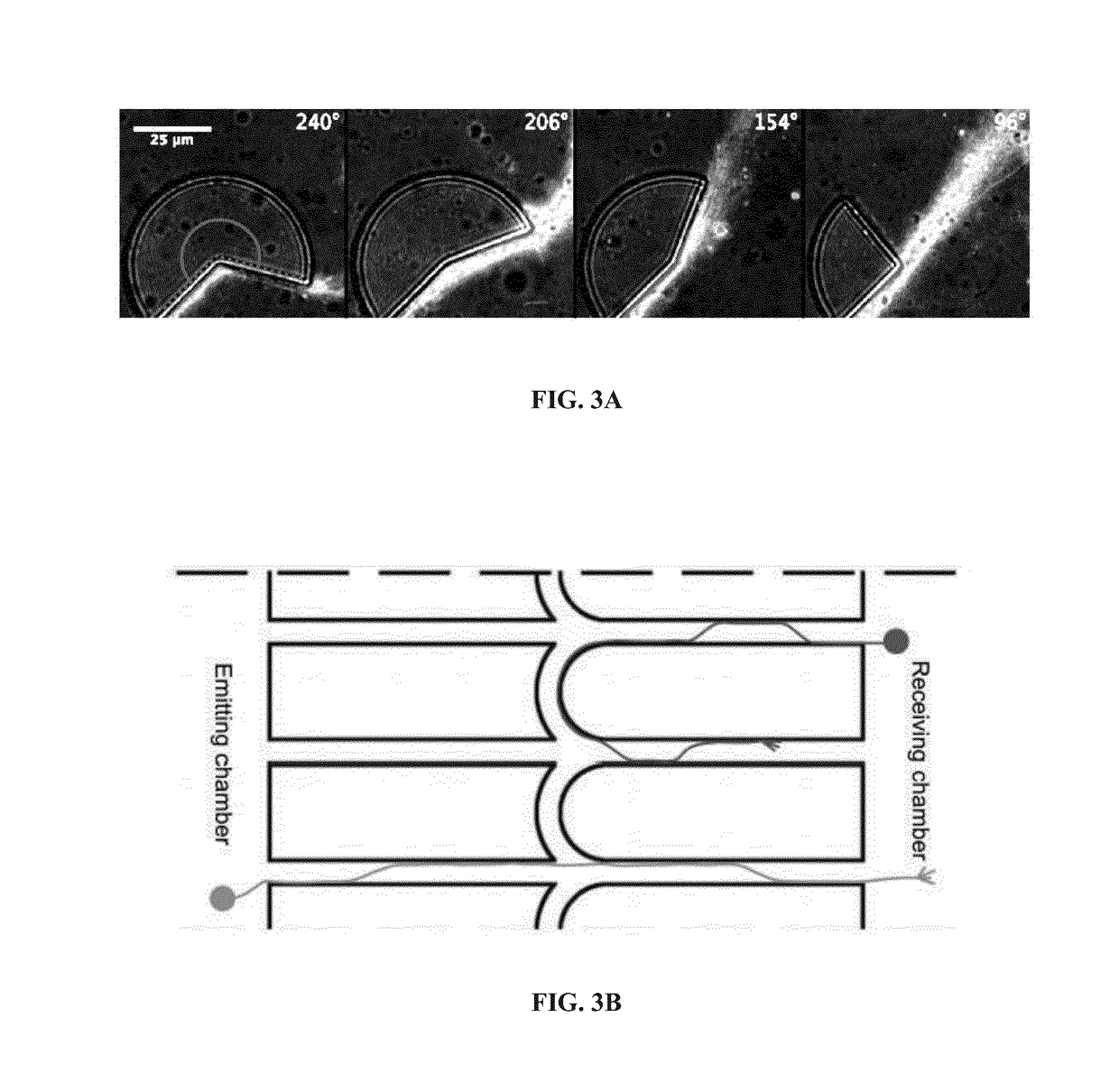
[0232]In the devices of the present invention, in contrast, selectivity can be obtained without any channel narrowing, avoiding the above disadvantages. FIG. 3A demonstrates a surprising property of axons, here evidenced by immunostaining of beta-tubulin, to follow preferentially the edges of guiding patterns provided these edges deviate away from the growth direction at a rate low enough. In particular, axons can follow the edges of structures even along cusps with angles smaller than 180° up to a certain critical angle (here between 154° and 96°). FIG. 3B shows an example of guiding patterns exploiting the edge affinity of axons to produce directional connectivity between neurons, from the emitting chamber to the receiving chamber, and the typical behavior of axons is such guiding patterns. Depending on whether they are growing from the emitting chamber or the receiving chamber, these axons behave differently at the interconnec...


PUM

PropertyMeasurementUnit
radius of gyrationaaaaaaaaaa

Abstract

The present invention relates to a microfluidic device to manipulate, select, treat, or cultivate living bodies, comprising a first chamber, a second chamber and a network of guiding tracks, wherein: said network of guiding tracks comprises at least one first guiding track connecting the first chamber and the second chamber and at least one second guiding track connecting said at least one first guiding track with at least two interconnections; and said at least one second guiding track comprises a curved part; said curved part exhibiting a concavity facing the second chamber or the part of the network connected to the second chamber.

Description

FIELD OF INVENTION[0001]The present invention relates to microfluidic devices and processes to cultivate cells or living bodies, in particular of neuronal cells. In some embodiments, it relates to microfluidic devices to control the shape of living bodies, or the connectivity between living bodies.BACKGROUND OF INVENTION[0002]Being able to cultivate in vitro various types of living bodies, notably biological neurons and any cell type that can give rise to neurons in controlled arrays will open the door to groundbreaking applications in many scientific fields. In fundamental science, this could be used to study signal processing by the brain, or brain development. In medicine, glucose-powered neural implants could repair cerebral functions. In vitro assays could also foster drug discovery and drug screening in the pharmaceutical industry. For instance cellular cultures can find applications as models to understand the cellular and molecular mechanisms at play in neuro-degenerative di...

Claims


Application Information

Patent Timeline
Patent Type & Authority Applications(United States)
IPC IPC(8): C12M1/00C12M3/06B01L3/00
CPCC12M47/04C12M23/16B01L3/502761B01L2300/0858B01L2300/088B01L2400/086B01L2300/0851B01L2200/0668B01L2300/087
Inventor VILLARD, CATHERINEVIOVY, JEAN-LOUISRENAULT, RENAUDDURAND, JEAN-BAPTISTEPEYRIN, JEAN-MICHELFERRANTE, IVAN
Owner INSTITUT CURIE
Why Eureka
Try Eureka