Low-Noise Multi-Propeller System

a multi-propeller, low-noise technology, applied in the direction of propellers, rotorcraft, vehicles, etc., can solve the problems of both thrust and torque, and the noise of rotational noise of the propeller may be significant, so as to reduce the pressure level of the far field, reduce the sound power, and reduce the sound power

Active Publication Date: 2020-04-09
NAT INST AEROSPACE ASSOC +1
View PDF3 Cites 2 Cited by
  • Summary
  • Abstract
  • Description
  • Claims
  • Application Information

AI Technical Summary

Benefits of technology

[0005]One aspect of the present invention is a system including two or more similar or substantially identical propellers that are located adjacent to each other, and operate at the same rotation rate and rotation direction with a predetermined angular phase offset between each propeller. The angular phase offset is uniquely defined based on the number of blades, and in some cases the number of propellers, to achieve a global (i.e. averaged in all directions) reduction in sound power of the fundamental tone at the blade passage frequency. The propellers are preferably phase-locked, and have the same rotation rate and rotation direction with a predetermined phase offset between each propeller. The propellers may be mechanically driven (e.g. utilizing belts / shafts) to maintain a desired phase relationship, or phase control can be achieved electronically (e.g. using a master / slave configuration and a control system to fix the relative phase between the propellers). In many cases, the optimal phase offset is 180-degrees divided by the number of blades of the propellers. For example, if the propellers have two blades, the optimal phase offset is exactly or about 90-degrees to thereby reduce sound power at the fundamental tone at the blade passage frequency. If the propellers have three blades, the optimal phase offset is 60-degrees. However, the optimal phase offset may be different for some configurations. For example, if the propeller system contains an odd number of propellers positioned near the vertices of a normal polygon (i.e. triangle, pentagon, etc.), then the preferred phase offset angle for adjacent propellers is: Δψr=180° / Nb−180° / (NpNb) where Nb is the number of blades and Np is the number of propellers. For two-bladed propellers in a triangle, the preferred phase offset is 60-degrees. The configuration of the propellers reduces far-field pressure levels due to the near-field acoustic interaction between the propellers. Adjacent propellers are phased to radiate less efficiently than a single acoustic source (e.g. a monopole). Additional propellers may also be phased to provide acoustic interaction that reduces the noise (sound pressure level) of the propellers in operation.

Problems solved by technology

Noise from the propellers may be significant, and may constitute a barrier for operations, particularly in populated areas.
Rotational noise is caused by both the thrust (and torque) produced by the propeller and by the displacement of air as the blades rotate.

Method used


Image

  • Low-Noise Multi-Propeller System
  • Low-Noise Multi-Propeller System
  • Low-Noise Multi-Propeller System

Examples


Embodiment Construction

[0022]For purposes of description herein, the terms “upper,”“lower,”“right,”“left,”“rear,”“front,”“vertical,”“horizontal,” and derivatives thereof shall relate to the invention as oriented in FIG. 1. However, it is to be understood that the invention may assume various alternative orientations and step sequences, except where expressly specified to the contrary. It is also to be understood that the specific devices and processes illustrated in the attached drawings, and described in the following specification, are simply exemplary embodiments of the inventive concepts defined in the appended claims. Hence, specific dimensions and other physical characteristics relating to the embodiments disclosed herein are not to be considered as limiting, unless the claims expressly state otherwise.

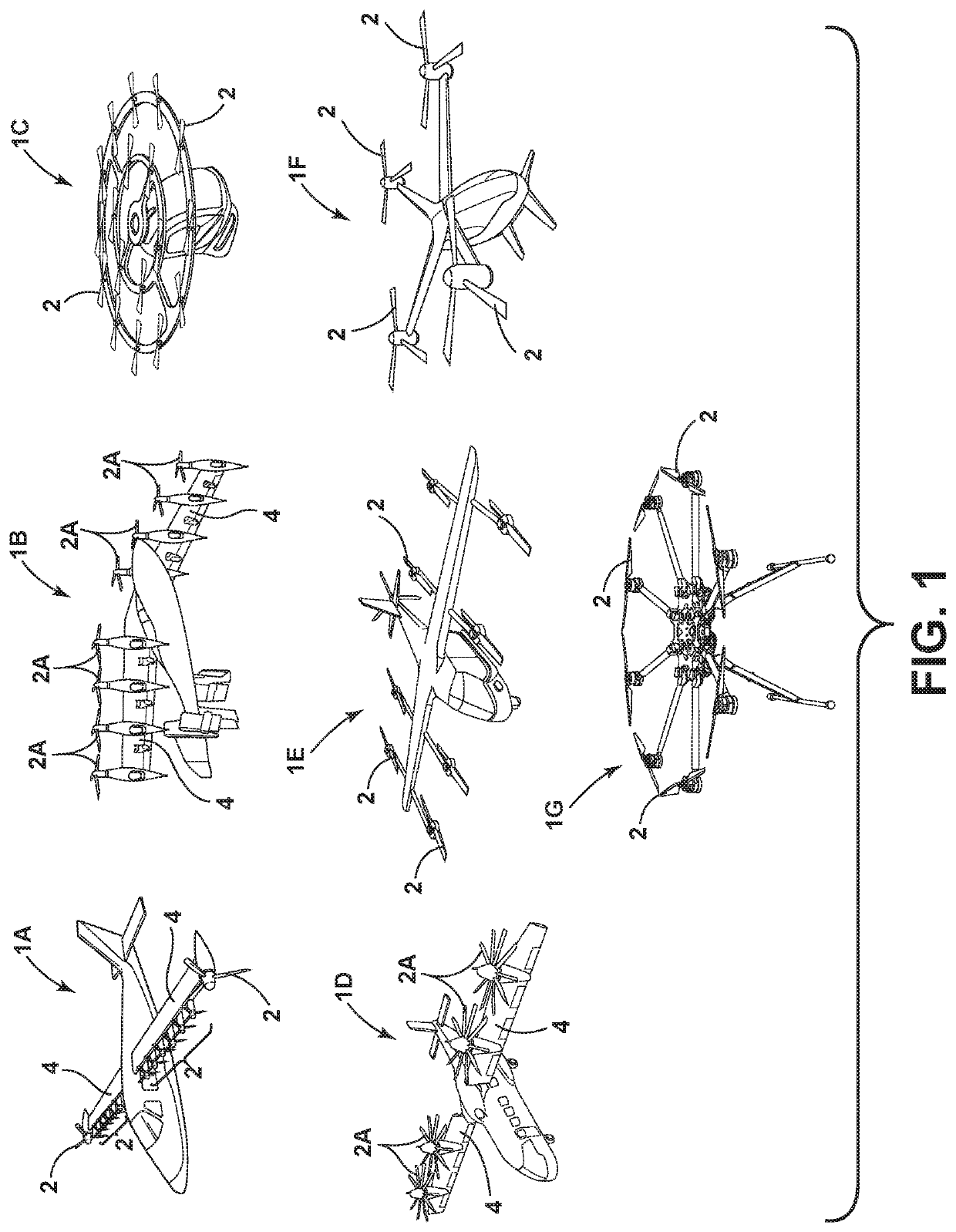
[0023]With reference to FIG. 1, aerial vehicles 1A-1G generally include vehicle bodies and powered drives (e.g. engines, motors) that drive a plurality of propellers 2 to provide lift and / or thrust. A...


PUM


Abstract

A low-noise multi-propeller system includes at least two propellers, each propeller including at least two blades. The propellers rotate in a first direction and define an angular phase relative to one another. A drive system corotates the propellers at substantially equal rotational rates in the first direction. The propellers are substantially phase-locked at a predefined relative phase offset that reduces the overall sound power of the fundamental tone at a blade passage frequency.

Description

CROSS-REFERENCE TO RELATED PATENT APPLICATION[0001]This application claims the benefit under 35 U.S.C. § 119(e) of U.S. Provisional Patent Application No. 62 / 743,005, filed Oct. 9, 2018, entitled “LOW-NOISE MULTI / ROTOR / PROPELLER SYSTEM,” which is incorporated herein by reference in its entirety.STATEMENT REGARDING FEDERALLY SPONSORED RESEARCH OR DEVELOPMENT[0002]The invention described herein was made in the performance of work under a NASA contract and by employees of the United States Government and is subject to the provisions of Public Law 96-517 (35 U.S.C. § 202) and may be manufactured and used by or for the Government for governmental purposes without the payment of any royalties thereon or therefore. In accordance with 35 U.S.C. § 202, the contractor elected not to retain title.BACKGROUND OF THE INVENTION[0003]Various types of manned and unmanned aerial vehicles have been developed. Aerial vehicles may be configured to provide forward flight and / or to take-off and land verti...

Claims


Application Information

Patent Timeline
Patent Type & Authority Applications(United States)
IPC IPC(8): B64C11/00B64C27/32
CPCB64C11/008B64C27/32B64C11/50
Inventor SCHILLER, NOAH H.ZAWODNY, NIKOLAS S.PASCIONI, KYLE A.RIZZI, STEPHEN A.
Owner NAT INST AEROSPACE ASSOC
Why Eureka
Try Eureka