Systems and methods for shortened corridor progressive lenses with superior distance vision area

a technology of progressive lenses and distance vision area, applied in the field of progressive lenses, can solve the problems of insufficient function of the near vision zone, and achieve the effect of enhancing the distance vision area

Inactive Publication Date: 2020-04-09
FGX INT
View PDF0 Cites 0 Cited by
  • Summary
  • Abstract
  • Description
  • Claims
  • Application Information

AI Technical Summary

Benefits of technology

[0007]The inventors have determined that a desirable trait for a truly “all-purpose” or “all-day” lens is an enhanced distance vision area that does not significantly compromise the functionality of the intermediate and near vision areas. Whereas some progressive lenses situate the fit point of the lens within a “valley” of astigmatic aberration, providing the wearer with a relatively narrow band of usable lens within the distance vision area, one principal of the inventive lens places the fit point relatively higher on the lens design, and maintains relatively clear (free from significant astigmatic aberrations) peripheral regions within the distance vision zone.
[0009]Additionally, the inventors have determined that shifting the corridor nasally provides a significant benefit as well. It is desirable, generally, to position the topographic features of the lens design such that, as the wearer's eyes track through the intermediate vision area into the near vision area, the wearer is not required to look through higher levels of cylinder (astigmatic aberration) than is strictly necessary. Using the previous example of an inventive lens with a 14 mm corridor length, based on adjusting the fit point of a designed 10 mm corridor, the astigmatic aberration on the nasal side of the intermediate vision area begins to encroach on the wearer's field of view. This is because the wearer's eyes tend to track inward as the wearer focuses on near objects, and the wearer's gaze will shift downward as the wearer adjusts the position of the lens to find the appropriate magnification for a near object. Accordingly, shifting the corridor nasally provides the wearer with a suitable meridian that passes through the lowest amount of astigmatism. Again using the previous example, the inventors have found that a 0.25 mm shift in the nasal direction is suitable.

Problems solved by technology

However, with modern frame styles dictating relatively short lens heights, merely moving the fit point higher on the lens can result in a near vision zone which is too small to function adequately.

Method used


Image

  • Systems and methods for shortened corridor progressive lenses with superior distance vision area
  • Systems and methods for shortened corridor progressive lenses with superior distance vision area
  • Systems and methods for shortened corridor progressive lenses with superior distance vision area

Examples


Embodiment Construction

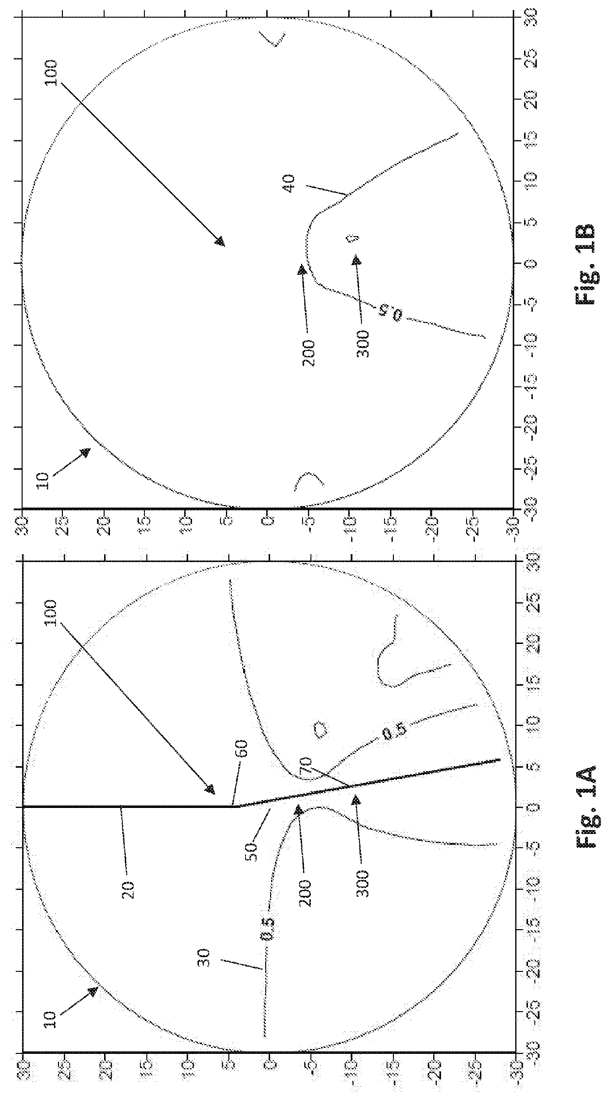
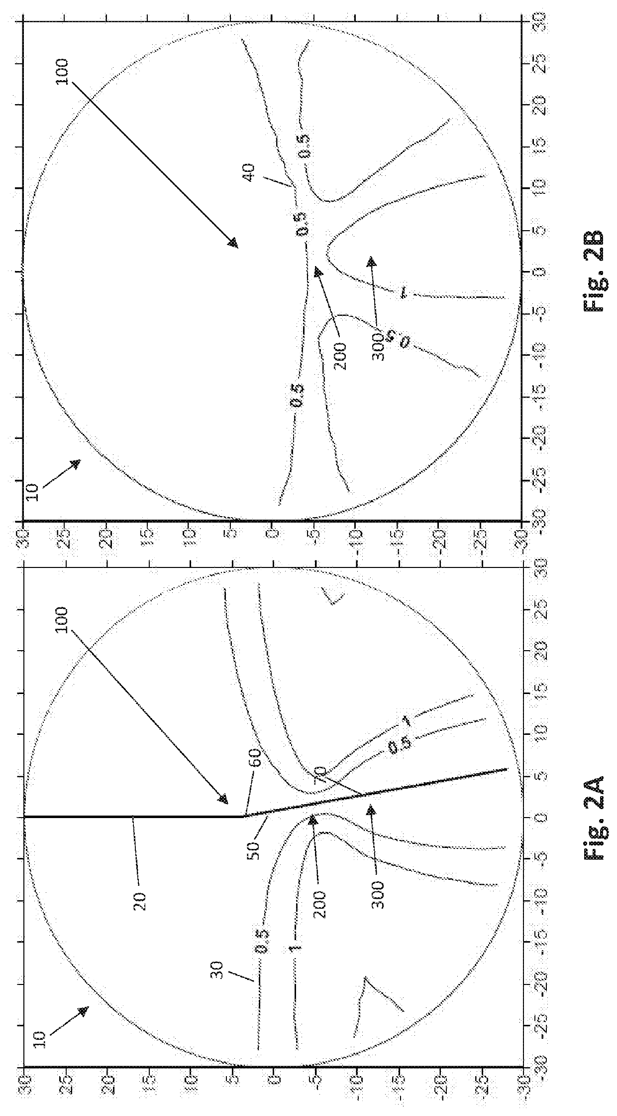
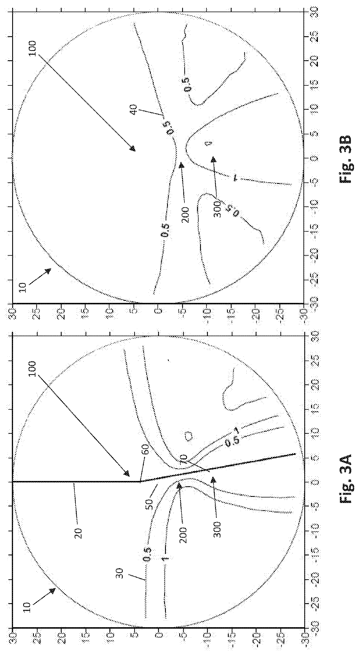
[0034]With reference to FIGS. 1A through 9B, depicted therein are various plots showing isocurves of various progressive lenses 10 according to several embodiments of the present invention, particularly progressive addition lenses 10 having maximum add powers ranging from 1.00 to 3.00. FIGS. 1A, 2A, 3A, 4A, 5A, 6A, 7A, 8A, and 9A are cylinder plots, with astigmatism isocurves 30 depicting the various levels of astigmatism throughout the lenses 10. FIGS. 1B, 2B, 3B, 4B, 5B, 6B, 7B, 8B, and 9B are mean power plots for the corresponding lenses 10, with magnification isocurves 40 depicting the various levels of magnification, or addition power, throughout the lens 10.

[0035]With continuing, general reference to FIGS. 1A through 9B, the various embodiments of the inventive lens 10 described and disclosed herein is a progressive lens 10 that, in at least one preferred embodiment, is intended to be fit on a wearer at 4 mm above the prism reference point (“PRP”) 50. With respect to the plots...


PUM


Abstract

The inventive lens includes a large distance vision area located at, and above, a wearer's natural “straight-ahead” gaze, a full power near vision area for, e.g., reading, and other activities, while accommodating a comfortable intermediate vision zone for transition magnification powers. One aspect of the inventive lens provides a shortened corridor design for a given fit point and reference point.

Description

CLAIM OF PRIORITY[0001]The present non-provisional patent application claims priority pursuant to 35 US.C. § 119(e) to currently pending and prior filed provisional patent application having U.S. Ser. No. 62 / 741,220, filed on Oct. 4, 2018, as well as to currently pending and prior filed provisional patent application having U.S. Ser. No. 62 / 855,471, filed on May 31, 2019, the contents of which are both explicitly incorporated herein, by reference, in their entireties.BACKGROUND OF THE INVENTIONField of the Invention[0002]The present invention relates to a progressive lenses and associated systems and methods.Description of the Related Art[0003]A progressive addition lens may be generally described as an ophthalmic lens including multiple areas with different powers of magnification, and which transitions “progressively” between these areas, in contrast to, e.g., a bifocal lens which includes two distinct magnification powers delineated by a sharp boundary. Typical progressive lenses...

Claims


Application Information

Patent Timeline
Patent Type & Authority Applications(United States)
IPC IPC(8): G02C7/06
CPCG02C7/066G02C7/021
Inventor RHEA, ERICMCCOLLUM, PATRICKMCROBERTS, RICHARD
Owner FGX INT
Why Eureka
Try Eureka