Anesthesia device and process for operating an anesthesia device

an anesthesia device and breathing gas technology, applied in the direction of inhalators, respirators, etc., can solve the problems of inconvenient operation, high cost, and inability to use breathing gas for reprocessing breathing circuits, etc., and achieve the effect of simple processing of anesthesia devices

Active Publication Date: 2014-01-14
DRAGERWERK AG
View PDF7 Cites 3 Cited by
  • Summary
  • Abstract
  • Description
  • Claims
  • Application Information

AI Technical Summary

Benefits of technology

[0005]The object of the present invention is therefore to make available an anesthesia device for respirating patients, by means of which the above-mentioned drawbacks are overcome. A special object of the present invention is to make available a process for operating the anesthesia device, by means of which a simple processing of the anesthesia device between the individual patients can be carried out.
[0013]An essential advantage of the anesthesia device according to the present invention is that no cost-intensive technical breathing gases, which are made available by the central gas supply system, are necessary for processing between the individual patient treatments. The breathing gas can be advantageously delivered from the breathing circuit by means of the ambient air, which is drawn in through an air inlet in the breathing circuit by the breathing gas delivery means. The breathing circuit of the anesthesia device according to the present invention comprises in this case an inspiratory breathing gas duct and an expiratory breathing gas duct, a Y-piece, which is designed as a closable Y-piece, for connecting the inspiratory and expiratory breathing gas ducts to the patient access. The Y-piece is typically closed by means of a sealing plug (or sealing cone). Furthermore, a central gas supply system for introducing breathing gas into the breathing circuit, a breathing gas delivery means, a breathing gas outlet duct with a breathing gas outlet valve, a breathing gas reservoir for intermediately storing breathing gas, a PEEP valve arranged upstream of the breathing gas reservoir in the direction of flow of the breathing gas, a breathing gas delivery means arranged downstream of the breathing gas reservoir in the direction of flow of the waste gas, an air inlet for introducing ambient air into the breathing circuit and a control means are provided. The air inlet is arranged between the PEEP valve and the breathing gas delivery means. The control means is used at least to control the ambient air entering through the air inlet, breathing gas delivery means, PEEP valve and breathing gas outlet valve for removing breathing gases from the breathing circuit. In a preferred embodiment, the air inlet is arranged such that it is arranged downstream of the breathing gas reservoir in the breathing circuit. A vacuum, which brings about a flow of the breathing gas present in the breathing gas reservoir through the breathing gas circuit to a breathing gas outlet duct, can thus be advantageously generated according to the process steps according to the present invention after closing the Y-piece and the PEEP valve, opening of the breathing gas outlet valve and the air inlet and after starting the breathing gas delivery means.
[0019]The anesthesia device according to the present invention may provide, furthermore, a CO2 absorber in the breathing circuit, which is preferably arranged downstream of the breathing gas reservoir. The breathing gas expired by the patient is separated from CO2 by means of a CO2 absorber. Moisture and heat are produced, among other things, during this separation. Together with the moisture expired by the patient, condensation may frequently occur within the breathing circuit. The functionality of the breathing circuit may be compromised because of the accumulation of this condensate over a plurality of consecutive applications. To remove this moisture, a drying effect of the breathing circuit is achieved in a next step of the process according to the present invention by repeating the process steps several times. This so-called drying phase ensures that the lime will not dry out completely within the CO2 absorber because of the ambient air used. In addition, a heater, which is advantageously operated at a higher heating output than in the normal patient respiration mode, may be provided within the breathing circuit. This advantageously leads to acceleration of drying.

Problems solved by technology

The breathing circuits of the anesthesia devices can be rinsed out pneumatically, as a rule, only poorly.
In particular, intolerance of the breathing gas already used may develop in the next patient.
The use of this technical breathing gas for reprocessing the breathing circuit is very cost-intensive.

Method used


Image

  • Anesthesia device and process for operating an anesthesia device
  • Anesthesia device and process for operating an anesthesia device
  • Anesthesia device and process for operating an anesthesia device

Examples


Embodiment Construction

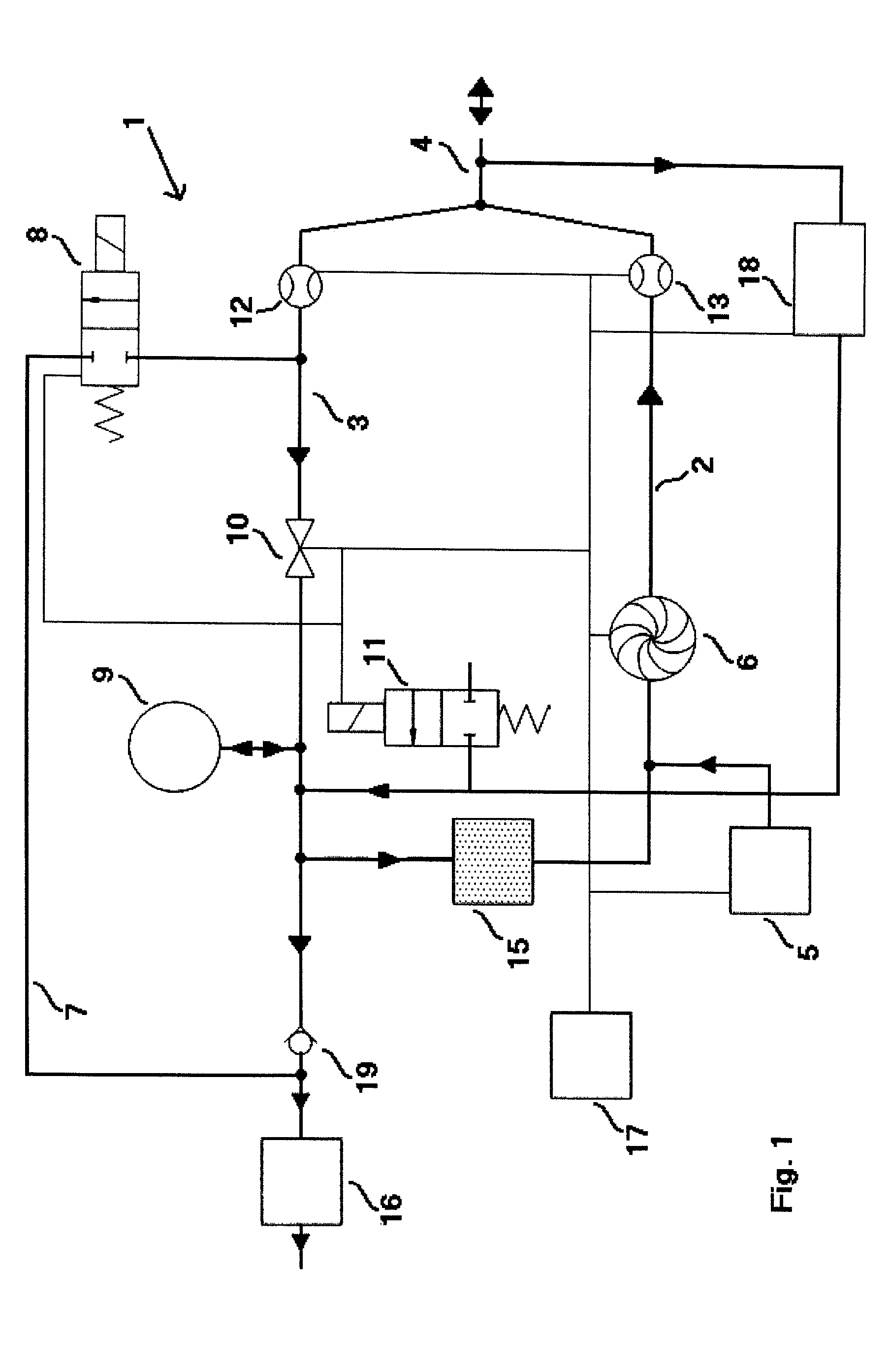
[0026]Referring to the drawings in particular, FIG. 1 shows a schematic view of the anesthesia device according to the present invention with a breathing circuit 1. Breathing circuit 1 is designed in the form of a rebreathing system, in which CO2 is removed from a breathing gas expired by the patient by a CO2 absorber. This breathing gas is subsequently added again to the inspiratory breathing gas. Only the breathing gas consumed by the patient is replaced in such a rebreathing system. The rest is reused from the expiratory breathing gas. The respective breathing gas pathways are indicated by bold lines in FIG. 1, whereas the thin lines represent control and data lines between the individual components of breathing circuit 1.

[0027]Breathing gas is fed to the breathing circuit 1 from a breathing gas supply system 5. The breathing gas is usually processed in the corresponding medical means and comprises essentially an oxygen-air mixture, N2O and volatile gaseous anesthetics. A breathi...


PUM


Abstract

An anesthesia device and a process are provided with which a breathing gas, which is present in a breathing circuit and which is especially enriched with an anesthetic, can be removed rapidly and in a cost-effective manner. The breathing circuit comprises an inspiratory breathing gas duct and an expiratory breathing gas duct, for receiving an expired breathing gas, a Y-piece, which is designed as a Y-piece that can be closed, for connecting the inspiratory and expiratory breathing gas ducts with a patient. At least one breathing gas supply system introduces breathing gas into the breathing circuit. A breathing gas outlet duct is provided with a breathing gas outlet valve. A breathing gas reservoir intermediately stores breathing gas. A PEEP valve is arranged upstream of the breathing gas reservoir in the direction of flow of the breathing gas. A breathing gas delivery is arranged downstream of the breathing gas reservoir in the direction of flow of the breathing gas. An air inlet introduces ambient air into the breathing circuit. The air inlet is arranged between the PEEP valve and the breathing gas delivery. A control is provided at least for controlling the ambient air entering through the air inlet, the breathing gas delivery, the PEEP valve and the breathing gas outlet valve for removing breathing gases from the breathing circuit.

Description

CROSS REFERENCE TO RELATED APPLICATIONS[0001]This application claims the benefit of priority under 35 U.S.C. §119 of European Patent Application EP 09 170 436.1 filed Sep. 16, 2009, the entire contents of which are incorporated herein by reference.FIELD OF THE INVENTION[0002]The present invention pertains to an anesthesia device, with which a breathing gas, which is contained in a breathing circuit and which is especially enriched with an anesthetic, can be rinsed out rapidly and in a cost-effective manner. The present invention is preferably suitable for rinsing out and drying the breathing circuit of the anesthesia device in order to process the breathing circuit with an appropriate control means between two patient treatments automatically or manually by an anesthesiologist or other medical staff. The present invention pertains, in particular, to a so-called rebreathing system, in which CO2 is removed from the expired breathing gas by means of a CO2 absorber and the remaining bre...

Claims


Application Information

Patent Timeline
Patent Type & Authority Patents(United States)
IPC IPC(8): A61M16/01
CPCA61M2016/0039A61M16/22A61M2016/0833A61M2016/1035A61M16/0066A61M16/01A61M2016/0042A61M2016/1015A61M16/009A61M2016/202A61M16/202A61M16/1015A61M16/0833A61M16/085
Inventor HEESCH, RALF
Owner DRAGERWERK AG
Why Eureka
Try Eureka