Wiring member

a technology of wiring member and wire, which is applied in the direction of insulated conductors, cables, conductors, etc., can solve the problems of cable becoming uncovered, the housing might not be able to be formed up to a position, etc., and achieves the effect of reducing the amount of resin used, and being easy to cover

Active Publication Date: 2020-04-09
SUMITOMO WIRING SYST LTD
View PDF2 Cites 5 Cited by
  • Summary
  • Abstract
  • Description
  • Claims
  • Application Information

AI Technical Summary

Benefits of technology

[0005]An object of the present disclosure is to provide a technique with which it is possible to suppress the occurrence of a cable becoming uncovered.
[0012]With these modes of the present disclosure, the occurrence of the cable becoming uncovered can be suppressed with use of the second protective portion. Here, the second protective portion is thinner than the first protective portion, and therefore it is possible to suppress the amount of resin used therein while maintaining a necessary level of protection.
[0015]With the fourth mode of the present disclosure, it is possible to reduce the amount of resin used in the portion of the first protective portion that is continuous with the second protective portion.
[0016]With the fifth mode of the present disclosure, it is possible to reduce the amount of resin used in the second protective portion. It also becomes easier to cover the second protective portion with the outer covering member.
[0017]With the sixth mode of the present disclosure, the connector can be attached to the end portion of the wire when the outer covering member has been shifted toward the second protective portion side. It is also possible to suppress the occurrence of the wire that extends from the resin molded portion becoming uncovered due to the outer covering member being shifted towards the connector side after being attached to the connector.

Problems solved by technology

Here, the housing might not be able to be formed up to a position reaching the end portion of the cable in a case such as where the end portion of the cable is to be attached to a connector after the housing is formed.
As a result, there is a risk of the cable becoming uncovered.

Method used


Image

  • Wiring member
  • Wiring member
  • Wiring member

Examples


Embodiment Construction

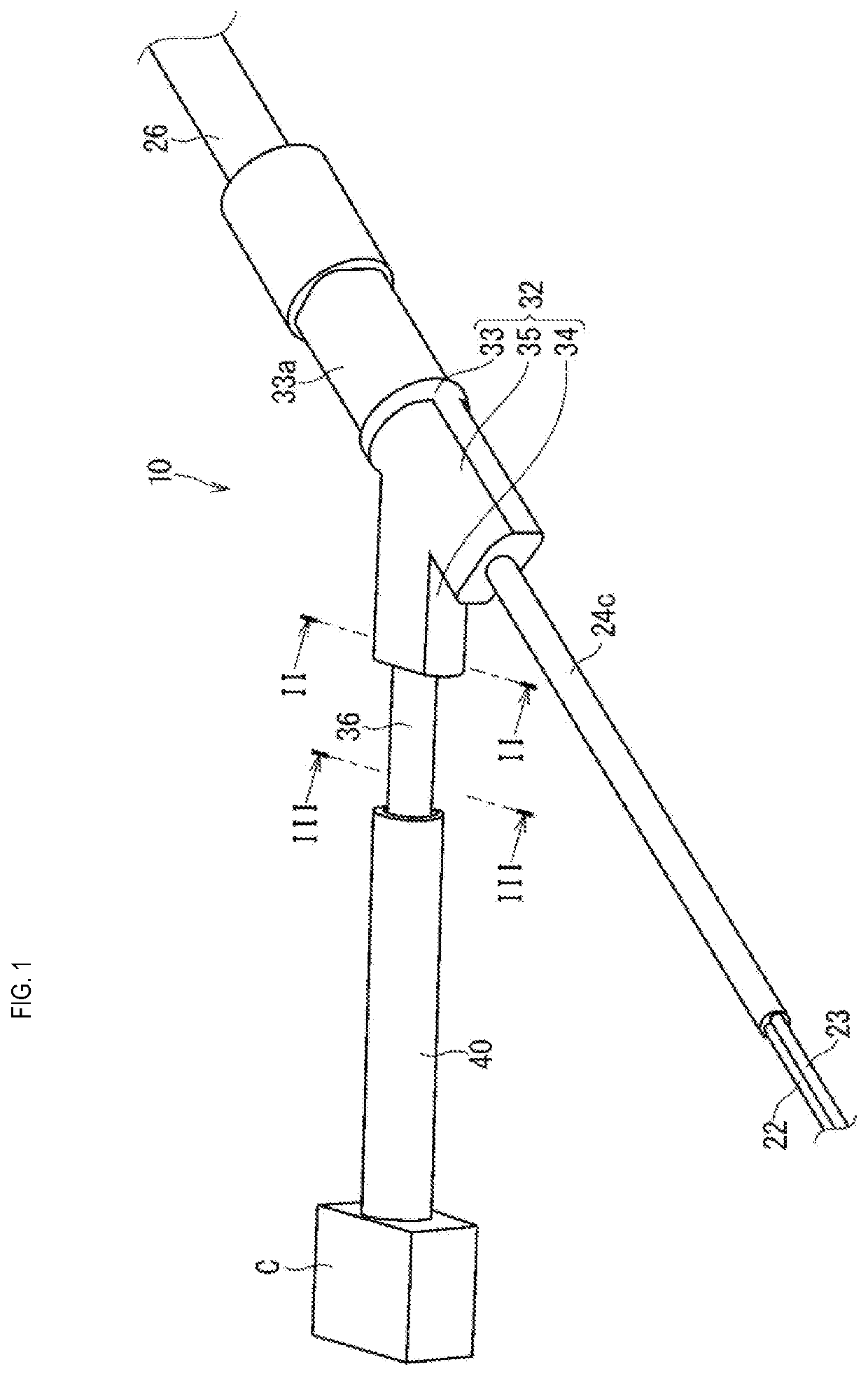
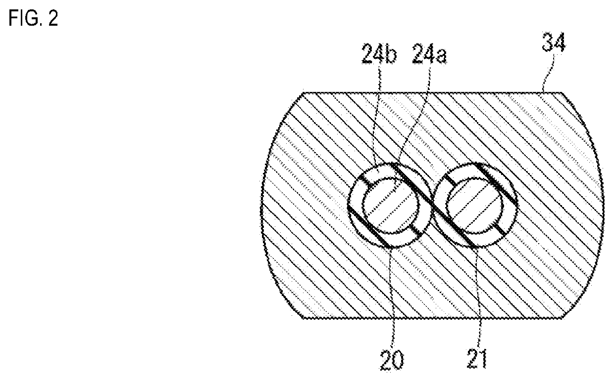
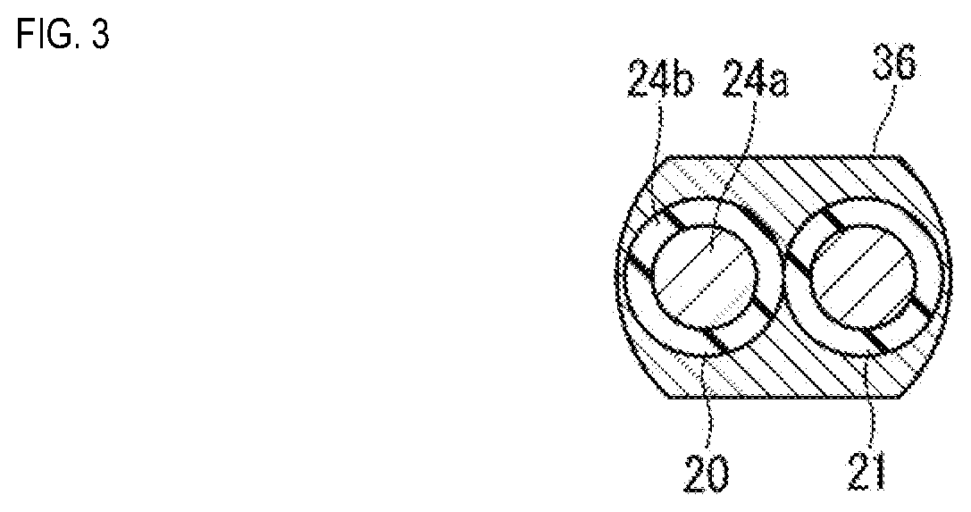
[0023]The following is a description of a wiring member according to an embodiment of the present disclosure. FIG. 1 is a perspective view showing a wiring member 10 according to the embodiment. FIG. 2 is a lateral cross-sectional view taken along a line II-II in FIG. 1. FIG. 3 is a lateral cross-sectional view taken along a line in FIG. 1. FIG. 4 is a longitudinal cross-sectional view showing the wiring member 10 according to the embodiment. FIG. 5 is an enlarged view of a portion of FIG. 4. Note that the wires and a connector shown in FIGS. 4 and 5 are not shown in cross-section.

[0024]The wiring member 10 includes wires 20, 21, 22, and 23, and a resin molded portion 30. Here, the wiring member 10 further includes an outer covering member 40.

[0025]The wiring member 10 may be provided with a single wire, or may be provided with the plurality of wires 20, 21, 22, and 23. Here, an example will be described in which the wiring member 10 includes the plurality of wires 20, 21, 22, and 2...


PUM

PropertyMeasurementUnit
lengthaaaaaaaaaa
shapeaaaaaaaaaa
conductiveaaaaaaaaaa

Abstract

An object of the present disclosure is to provide a technique with which it is possible to prevent the occurrence of a cable becoming uncovered. A wiring member includes wires, and a resin molded portion. The resin molded portion includes a first protective portion configured to cover an intermediate portion of the wires, and a second protective portion that is formed thinner than the first protective portion and is configured to be continuous with and cover a lending end side of the wires and relative to first protective portion. For example, the wiring member further includes an outer covering member that covers the second protective portion and the wires that extend from the second protective portion.

Description

CROSS-REFERENCE TO RELATED APPLICATIONS[0001]This application claims priority of Japanese Patent Application No. JP 2018-190693 filed Oct. 9, 2018.[0002]This disclosure relates to a wiring member.BACKGROUND ART[0003]JP 2007-95439A discloses a technique to connect an electrically insulated cable to a main apparatus, seal an end portion of the electrically insulated cable on the main apparatus side thereof and the main apparatus together with use of a provided housing, which is formed through injection molding polyester resin. The outermost layer of the covering of the end portion of the cable is thus bonded together with the housing, and the cable and the housing are thus hermetically sealed.SUMMARY[0004]Here, the housing might not be able to be formed up to a position reaching the end portion of the cable in a case such as where the end portion of the cable is to be attached to a connector after the housing is formed. In such a case, it is conceivable to protect the end portion side...

Claims


Application Information

Patent Timeline
Patent Type & Authority Applications(United States)
IPC IPC(8): H01B7/18H01B3/30
CPCH01B7/1875H01B3/308B60R16/0215H02G3/04H02G3/0406H02G3/32H02G15/025B60R16/0207
Inventor YAMAMOTO, HIRONOBUKIM, KYUNGWOOKOBAYASHI, TOSHINARI
Owner SUMITOMO WIRING SYST LTD
Why Eureka
Try Eureka