Image forming system and control program

a technology of image forming system and control program, which is applied in the direction of digital output to print units, instruments, computing, etc., can solve problems such as operation error by users, and achieve the effect of preventing a setting error of an output mod

Inactive Publication Date: 2020-04-09
KONICA MINOLTA INC
View PDF5 Cites 1 Cited by
  • Summary
  • Abstract
  • Description
  • Claims
  • Application Information

AI Technical Summary

Benefits of technology

[0008]The present invention has been made in view of such circumstances and an object of the present invention is to provide an image forming system and a control program capable of preventing a setting error of an output mode by a user when newly generating a correct image.

Problems solved by technology

However, conventionally, since there is a selection button for a mode capable of printing a plurality of copies such as a normal mode in addition to the proof mode on an output mode setting screen setting the output mode of the print job, there is a possibility that an operation error by the user may occur when generating a new correct image.

Method used


Image

  • Image forming system and control program
  • Image forming system and control program
  • Image forming system and control program

Examples


embodiments

[0028]100>

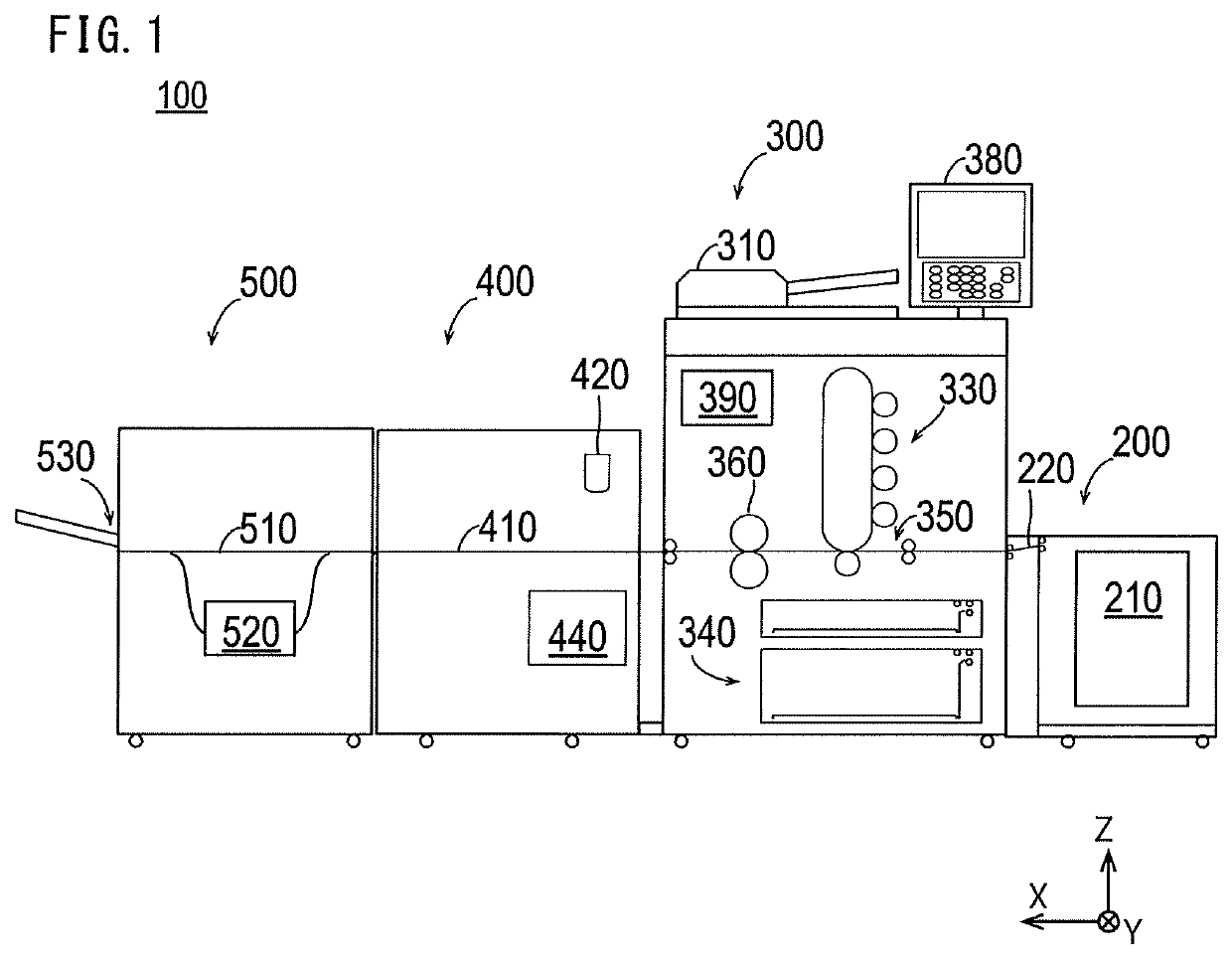
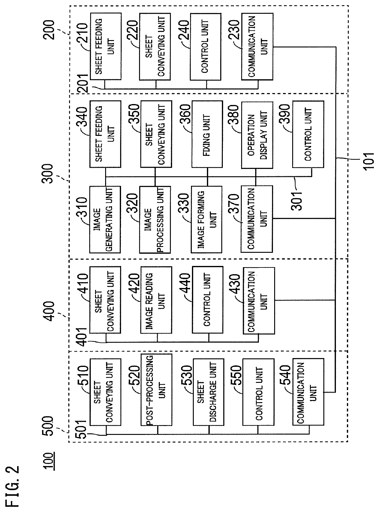
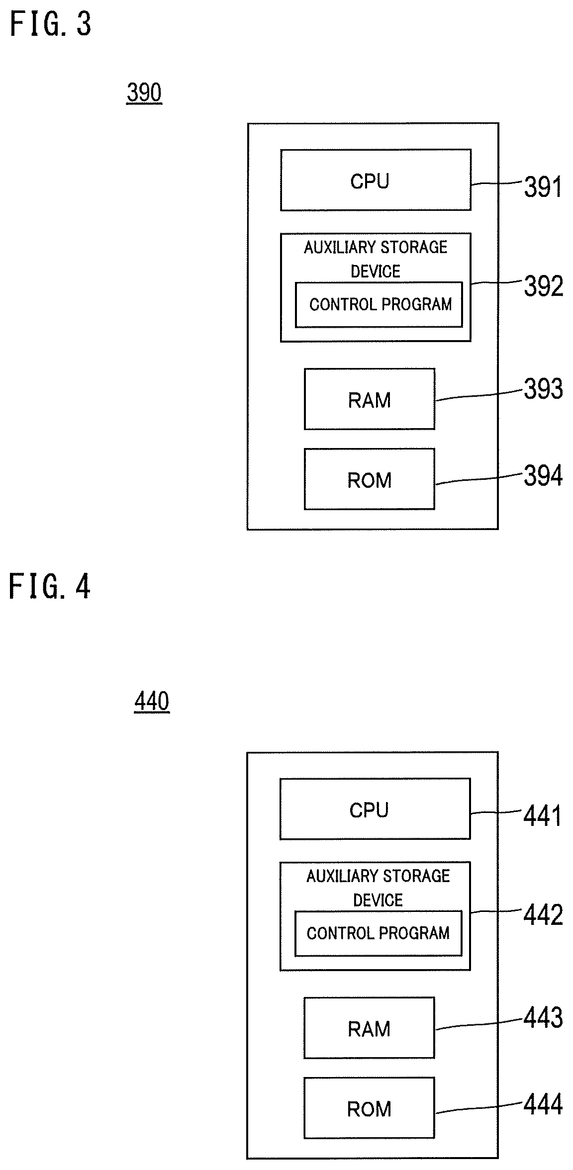
[0029]FIG. 1 is a schematic cross-sectional view of an image forming system 100 of an embodiment and FIG. 2 is a schematic block diagram of the image forming system 100 illustrated in FIG. 1. Further, FIG. 3 is a schematic block diagram illustrating a configuration of a control unit 390 of an image forming apparatus 300 illustrated in FIG. 2 and FIG. 4 is a schematic block diagram illustrating a configuration of a control unit 440 of a first post-processing apparatus 400 illustrated in FIG. 2.

[0030]As illustrated in FIG. 1, the image forming system 100 of the embodiment includes a sheet feeding apparatus 200, an image forming apparatus 300, a first post-processing apparatus 400, and a second post-processing apparatus 500 which are connected in series in the X direction (the sheet conveying direction). Additionally, the configuration of the image forming system 100 illustrated in FIG. 1 is an example and the type and the number of apparatuses included in the image forming s...

modified example 1

[0093]FIG. 13 is a schematic diagram illustrating a modified example of correct image setting. In the modified example, it is assumed that the “inspection setting” is “ON”, the “correct image setting” is “selecting from registered images”, and no registered image is specified.

[0094]In this state, when the instruction to start printing is received, the “correct image setting” is selected from the “registered images”. However, since the registered images do not exist, the correct image cannot be selected from the registered images. Here, the control unit 390 performs control so that a correct image is newly generated in such a case.

[0095]Additionally, the “output mode setting” screen 607 may be configured to function as a notification unit so as to notify the user of the printing in an output mode (for example, a proof mode) of printing only one copy of the image of the print job.

modified example 2

[0096]In the above-described example, the case of printing one copy of the image of the print job by the “proof” mode when newly generating the correct image has been described, but one copy of the image of the print job can be printed by a “sample output” mode. FIG. 14 is a schematic diagram illustrating the case of printing one copy of the image of the print job by the “sample output” mode.

[0097]In the modified example, it is assumed that the “inspection setting” is “ON” and the “correct image setting” is “new generating”. When the user selects a “sample output” button 618 of the “job ticket editing” screen 600, a “sample output setting” screen 619 is launched.

[0098]When the correct image is newly generated, only the condition of “outputting one copy” can be selected in the “sample output” mode. Thus, “sheet output” and “specify sheet” other than “one copy output” are grayed out and cannot be selected by the user. When the “OK” button 620 is selected, the sample output is started....


PUM


Abstract

Provide is an image forming system and a control program capable of preventing a setting error of an output mode by a user when newly generating a correct image. An image forming system includes an image forming unit, an image reading unit, a reference image acquiring unit, and a control unit. The image reading unit reads the image on the sheet formed by the image forming unit. The reference image acquiring unit acquires a reference image as a reference for determining whether the image of the print job formed on the sheet is normal. The control unit prohibits forming of a plurality of copies of the image of the print job by the image forming unit when the reference image acquiring unit newly generates and acquires a reference image by reading the image formed on the sheet by the image forming unit using the image reading unit.

Description

CROSS-REFERENCE TO RELATED APPLICATION[0001]The entire disclosure of Japanese Patent Application No. 2018-188113, filed on Oct. 3, 2018, is incorporated herein by reference in its entirety.BACKGROUND1. Technological Field[0002]The present invention relates to an image forming system and a control program.2. Description of the Related Art[0003]In recent years, in the production / printing field, there has been an active development of a technology in order to improve printing quality and stabilize image quality. As one of such technologies, there is an image forming system having an automatic inspection function for automatically inspecting an image of a printed material.[0004]In such an image forming system, it is determined whether a printed material of a main printing has sufficient quality by comparing an image of a printed material confirmed by a user to have good image quality (hereinafter referred to as “quality”) with an image obtained by scanning the printed material of the ma...

Claims


Application Information

Patent Timeline
Patent Type & Authority Applications(United States)
IPC IPC(8): H04N1/32G06F3/12H04N1/00
CPCG06F3/1256H04N1/32609H04N1/00074G06F3/1208G06F3/1219G06F3/1239G06F3/1285H04N1/32657
Inventor SHIMURA, HIROSHI
Owner KONICA MINOLTA INC
Why Eureka
Try Eureka