Aerosol delivery device with improved connectivity, airflow, and aerosol paths

a technology of aerosol path and delivery device, which is applied in the direction of ohmic resistance waterproof/airtight seal, coupling device connection, magnetic body, etc., can solve the problems of delivering considerable quantities of incomplete combustion and pyrolysis products

Active Publication Date: 2020-04-16
RAI STRATEGIC HLDG INC
View PDF0 Cites 20 Cited by
  • Summary
  • Abstract
  • Description
  • Claims
  • Application Information

AI Technical Summary

Benefits of technology

[0062]These and other features, aspects, and advantages of the disclosure will be apparent from a reading of the following detailed description together with the accompanying drawings, which are briefly described below. The invention includes any combination of two, three, four, or more of the above-noted embodiments as well as combinations of any two, three, four, or more features or elements set forth in this disclosure, regardless of whether such features or elements are expressly combined in a specific embodiment description herein. This disclosure is intended to be read holistically such that any separable features or elements of the disclosed invention, in any of its various aspects and embodiments, should be viewed as intended to be combinable unless the context clearly dictates otherwise.

Problems solved by technology

Many of those devices purportedly have been designed to provide the sensations associated with cigarette, cigar, or pipe smoking, but without delivering considerable quantities of incomplete combustion and pyrolysis products that result from the burning of tobacco.

Method used


Image

  • Aerosol delivery device with improved connectivity, airflow, and aerosol paths
  • Aerosol delivery device with improved connectivity, airflow, and aerosol paths
  • Aerosol delivery device with improved connectivity, airflow, and aerosol paths

Examples


Embodiment Construction

[0110]The present disclosure will now be described more fully hereinafter with reference to example embodiments thereof. These example embodiments are described so that this disclosure will be thorough and complete, and will fully convey the scope of the disclosure to those skilled in the art. Indeed, the disclosure may be embodied in many different forms and should not be construed as limited to the embodiments set forth herein; rather, these embodiments are provided so that this disclosure will satisfy applicable legal requirements. As used in the specification, and in the appended claims, the singular forms “a”, “an”, “the”, include plural referents unless the context clearly dictates otherwise.

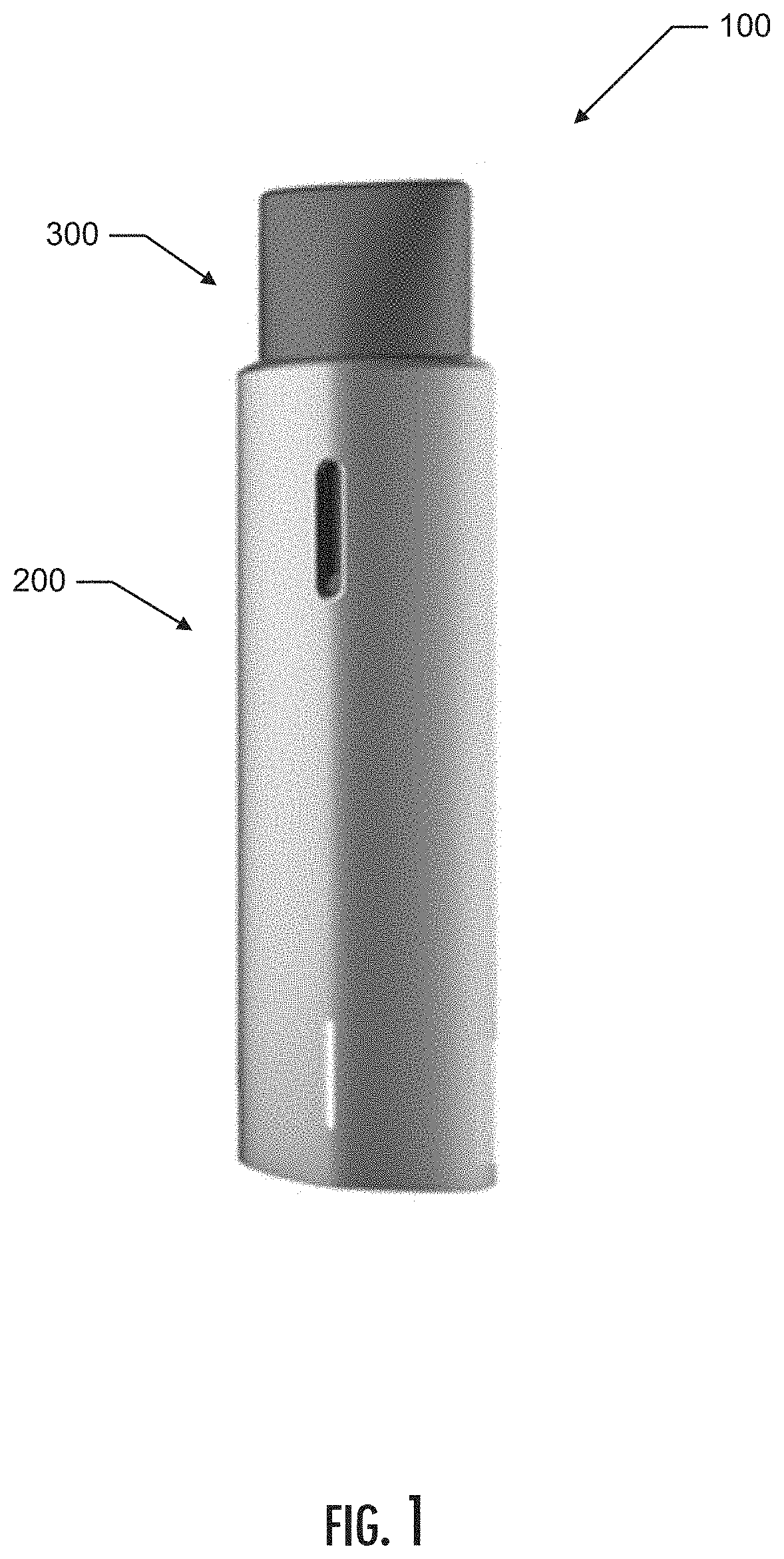
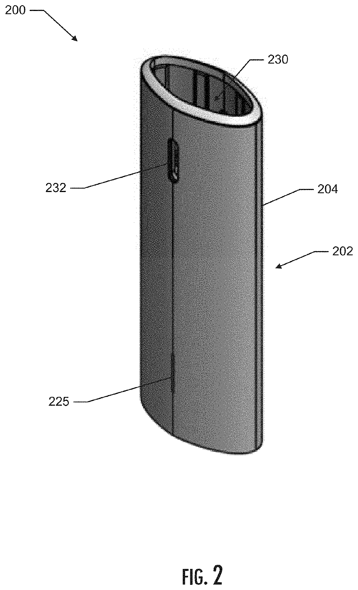
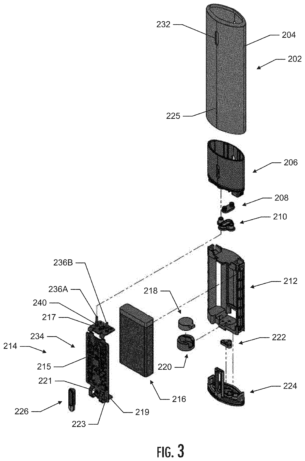
[0111]As described hereinafter, embodiments of the present disclosure relate to aerosol delivery devices or vaporization devices, said terms being used herein interchangeably. Aerosol delivery devices according to the present disclosure use electrical energy to heat a material (preferably ...


PUM


Abstract

The present disclosure provides an aerosol delivery device and a cartridge for an aerosol delivery device. In various implementations, the aerosol delivery device comprises a control device that includes an outer housing defining a cartridge receiving chamber, and further includes a power source and a control component, and a cartridge that includes a mouthpiece, a tank, a heating assembly, and a bottom cap. The mouthpiece defines an exit portal in an end thereof, and the tank is configured to contain a liquid composition therein. The cartridge is configured to be removably coupled with the receiving chamber of the control device, and the heating assembly defines a vaporization chamber and is configured to heat the liquid composition to generate an aerosol. An inlet airflow is defined by a gap between the cartridge and the control device that originates at an interface between an outer peripheral surface the mouthpiece and control device.

Description

CROSS-REFERENCE TO RELATED APPLICATIONS[0001]This application claims priority to, and the benefit of, U.S. Provisional Patent Application No. 62 / 744,978, titled Aerosol Forming Device, filed on Oct. 12, 2018, and U.S. Provisional Patent Application No. 62 / 911,519, titled Aerosol Delivery Device with Improved Connectivity, Airflow, and Aerosol Paths, filed on Oct. 7, 2019, each of which is incorporated herein in its entirety by reference.TECHNOLOGY FIELD[0002]The present disclosure relates to aerosol delivery devices such as smoking articles, and more particularly to aerosol delivery devices that may utilize electrically generated heat for the production of aerosol (e.g., smoking articles commonly referred to as electronic cigarettes). The smoking articles may be configured to heat an aerosol precursor, which may incorporate materials that may be made or derived from tobacco or otherwise incorporate tobacco, the precursor being capable of forming an inhalable substance for human cons...

Claims


Application Information

Patent Timeline
Patent Type & Authority Applications(United States)
IPC IPC(8): A24F47/00A61M11/04H05B3/06H05B3/22
CPCH05B3/22A61M2205/3331A24F47/008A61M11/042A61M2205/0288H05B3/06H01R31/06A24F40/10A24F40/42A24F40/46A24F40/485H01R13/6205H01R13/005H05B3/42H05B2203/021H05B2203/022H05B3/04H05B3/34H05B2203/019H05B2203/02H05B2203/013H05B3/145A61M2205/582A61M2205/583A61M2205/8206A61M2205/8237A61M2016/0021A61M15/06A61M15/0021A61M2205/3653A61M2016/0027A24F7/00A24F40/50A24F40/51H01F7/00H05B1/0269H01R33/18H01R33/945H05B3/46
Inventor NOVAK, III, CHARLES JACOBDAUGHERTY, SEAN A.ALLER, JAREDGALLOWAY, MICHAEL RYANHOLT, JUSTINNETTENSTROM, MATTHEW JOELSCHENNUM, STEVEN MICHAEL
Owner RAI STRATEGIC HLDG INC
Why Eureka
Try Eureka