

Combustor liner attachment assembly for gas turbine engine
Patent Information
- Authority / Receiving Office
- US · United States
- Current Assignee / Owner
- RAYTHEON TECH CORP
- Publication Date
- 2020-04-16
Smart Images
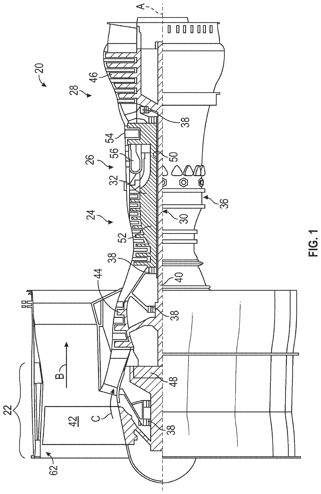
Figure 1 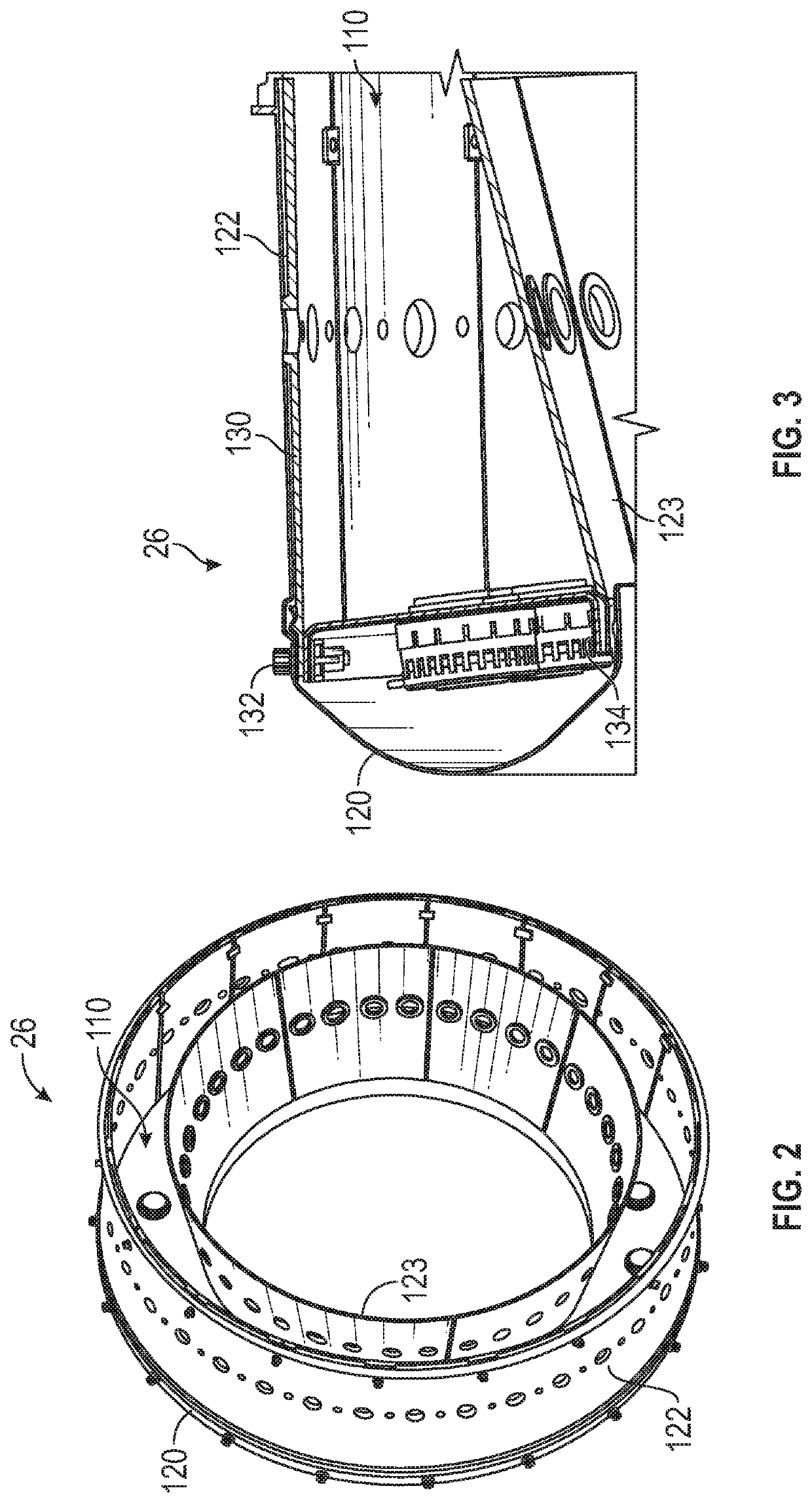
Figure 2 
Figure 3
Abstract
Description
BACKGROUND
[0001] Exemplary embodiments pertain to the art of gas turbine engines and, more particularly, to a combustor liner attachment assembly for gas turbine engines.
[0002] Gas turbine engines are generally known and, when used on an aircraft, typically include a fan delivering air into a bypass duct and a compressor section. Air from the compressor section is passed downstream into a combustion section where it is mixed with fuel and ignited. Products of this combustion pass downstream over turbine rotors driving the turbine rotors to rotate.
[0003] Some existing gas turbine engines utilize a metallic bulkhead within the combustion section. The metallic bulkhead is either made as a single integral unit, or assembled from multiple bulkhead panels. In order to combat high temperatures, engines have been designed using materials other than metal to create the combustor itself or using a liner made from an alternate material within the combustor and affixed to the combustor via fastene...