Guidewire Delivery of Transcatheter Heart Valve

a transcatheter heart valve and guidewire technology, applied in the field of delivery system for deployment of prosthetic valves, can solve the problems of prone to fracture of the struts of the valve, not fully correcting the valve problem, and placing the valve in the descending aorta instead of the heart itsel

a transcatheter heart valve and guidewire technology, applied in the field of delivery system for deployment of prosthetic valves, can solve the problems of prone to fracture of the struts of the valve, not fully correcting the valve problem, and placing the valve in the descending aorta instead of the heart itsel

US20200121458A1Active Publication Date: 2020-04-23VDYNE INC

Image

  • Guidewire Delivery of Transcatheter Heart Valve
  • Guidewire Delivery of Transcatheter Heart Valve
  • Guidewire Delivery of Transcatheter Heart Valve

Examples


Embodiment Construction

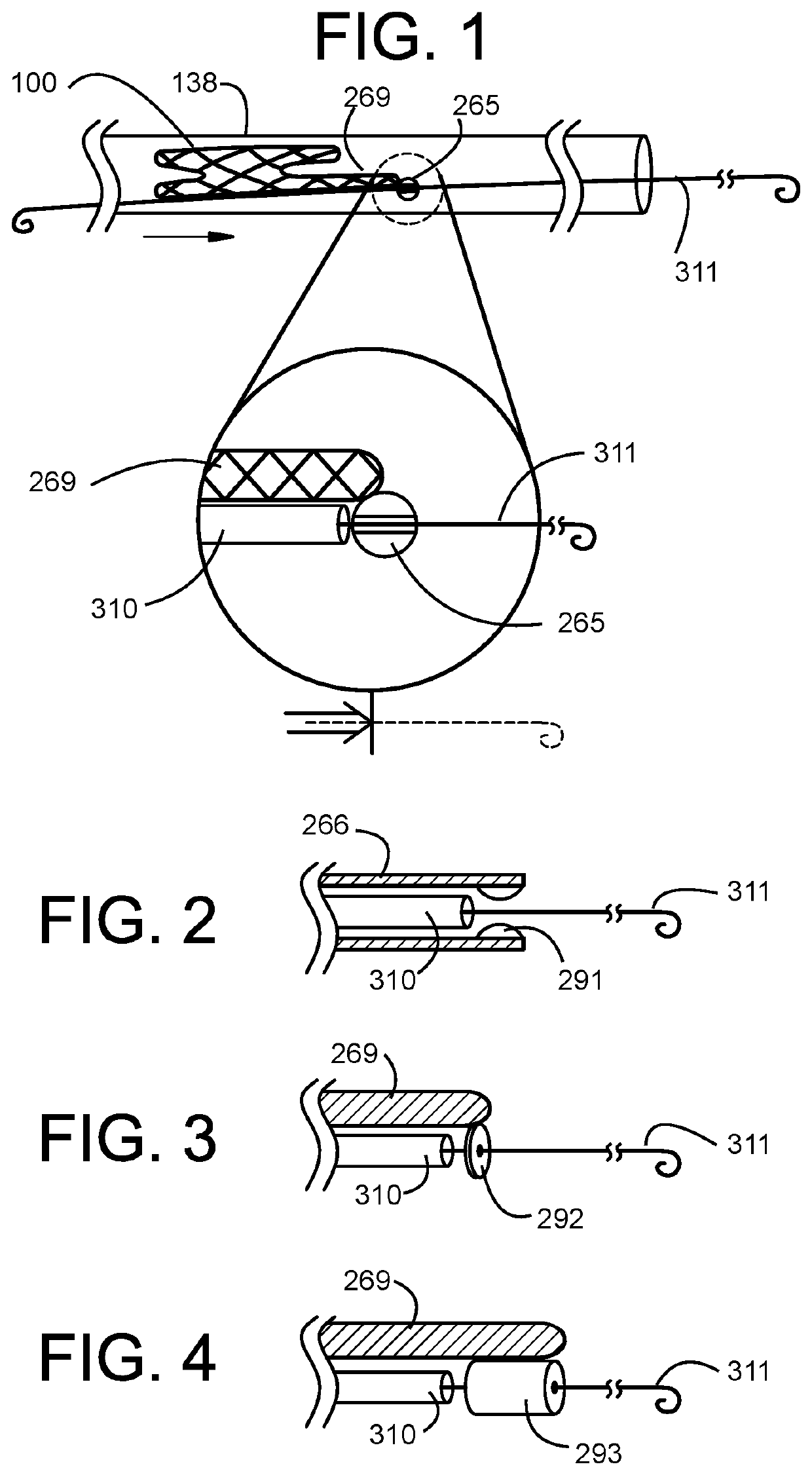
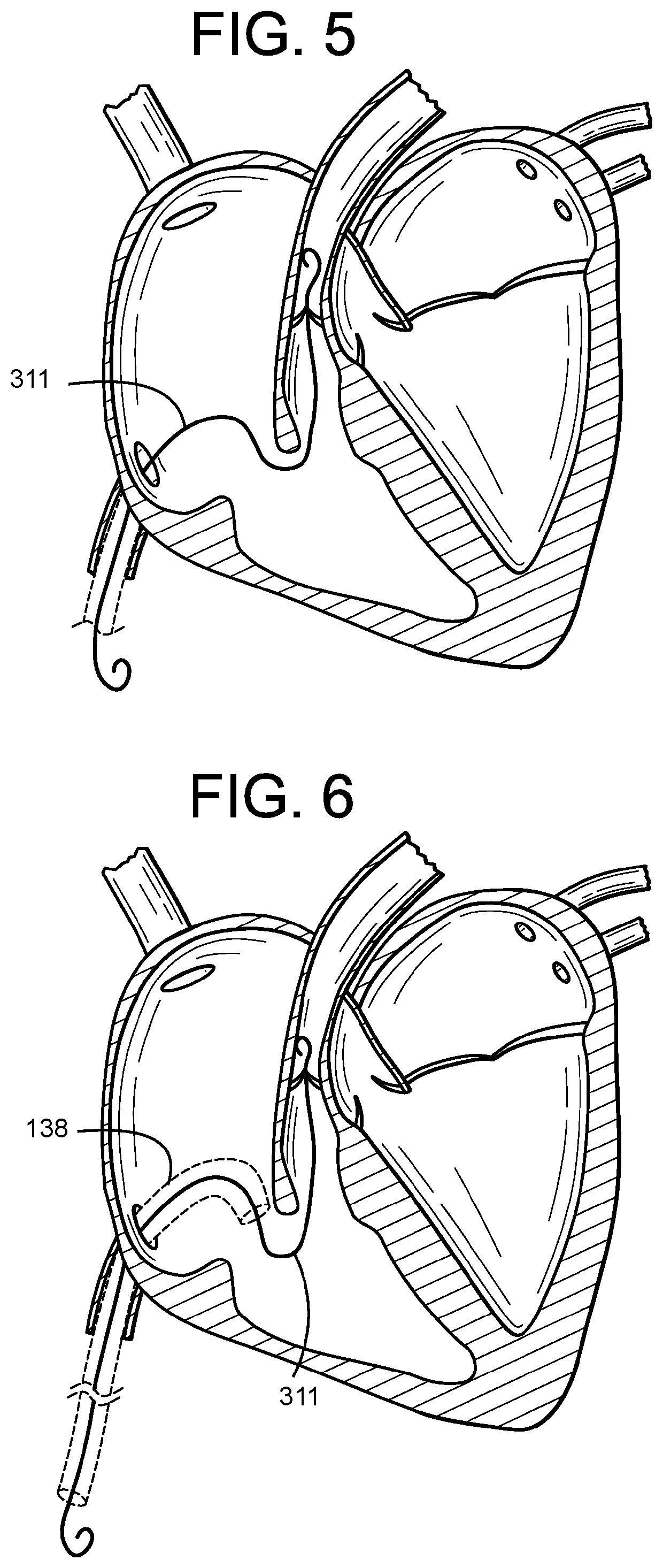
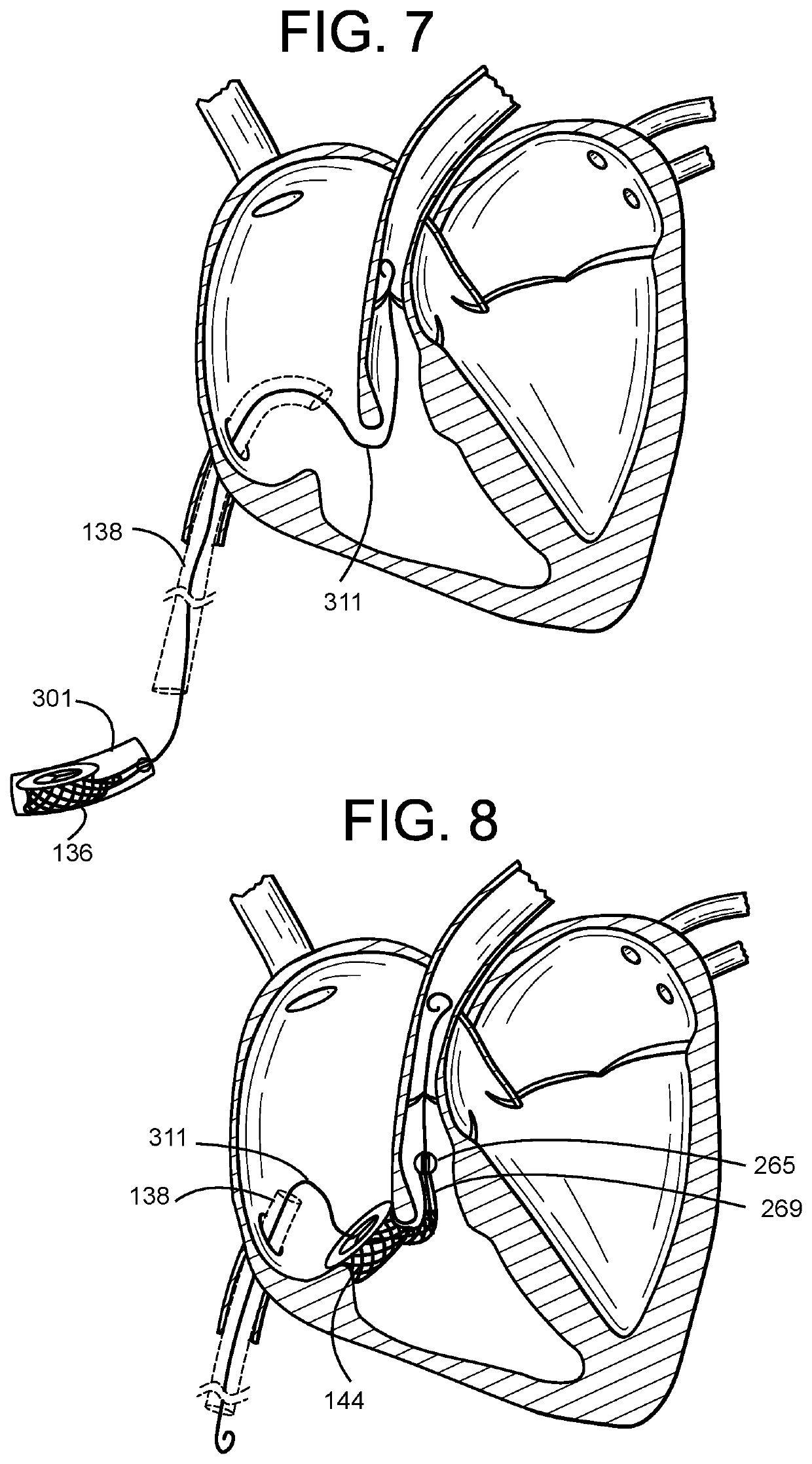
[0086]The invention is directed to a transcatheter heart valve replacement that is a low profile, orthogonally delivered implantable prosthetic valve having an ring-shaped tubular frame, an inner 2- or 3-panel sleeve, an elongated sub-annular tension arm extending into the right ventricular outflow tract, and one or more anchor elements.

[0087]The embodiments herein and the various features and advantageous details thereof are explained more fully with reference to the non-limiting embodiments that are illustrated in the accompanying drawings and detailed in the following description. Descriptions of well-known components and processing techniques are omitted so as to not unnecessarily obscure the embodiments herein. The examples used herein are intended merely to facilitate an understanding of ways in which the embodiments herein may be practiced and to further enable those of skill in the art to practice the embodiments herein. Accordingly, the examples should not be construed as l...


PUM


Abstract

The invention relates to delivery system for deployment of a prosthetic valve, having a hypotube sheathed guidewire assembly having an outer sheath and an inner guidewire shaft that pushes against a guidewire collar on a tension arm of a compressed transcatheter valve to deliver the valve and position the valve to the RVOT or other location in the body.

Description

CROSS-REFERENCE TO RELATED APPLICATIONS[0001]Provided by Application Data Sheet per USPTO rules.STATEMENT REGARDING FEDERALLY SPONSORED R&D[0002]Provided by Application Data Sheet per with USPTO rules.NAMES OF PARTIES TO JOINT RESEARCH AGREEMENT[0003]Provided by Application Data Sheet per with USPTO rules.REFERENCE TO SEQUENCE LISTING[0004]Provided by Application Data Sheet per USPTO rules.STATEMENT RE PRIOR DISCLOSURES[0005]Provided by Application Data Sheet per USPTO rules.BACKGROUND OF THE INVENTIONField of the Invention[0006]The invention relates to delivery system for deployment of a prosthetic valve, having a hypotube sheathed guidewire assembly having an outer sheath and an inner guidewire shaft that pushes against a guidewire collar on a tension arm of a compressed transcatheter valve to deliver the valve and position the valve to the tricuspid valve or mitral valve location in the body.DESCRIPTION OF THE RELATED ART[0007]In 1952 surgeons implanted the first mechanical heart...

Claims


Application Information

Patent Timeline
23 Apr 2020
Publication
US20200121458A1
IPC
A61F2/24
CPC
A61F2210/0014; A61F2/2436; A61F2/2418; A61F2/2466; A61F2/2433; A61F2/2439; A61F2220/0008; A61F2230/0095
Inventors
VIDLUND, ROBERT; CHRISTIANSON, MARK