Holding unit and mold extrusion mechanism provided with holding unit

Active Publication Date: 2020-04-23
TECHNOCRATS CORP
View PDF0 Cites 2 Cited by
  • Summary
  • Abstract
  • Description
  • Claims
  • Application Information

AI Technical Summary

Benefits of technology

[0027]According to the present invention, the retaining mechanism is unitized, and therefore, can be easily incorporated into the mold and has high usability. In addition, the retaining unit of the present invention is configured such that the pressing unit for engaging the first member with the second member is attachable and detachable, and the pressing force thereof is adjustable in a state in which the pressing unit is incorporated into the first member. Therefore, the retaining unit can be used by being incorporated into various molds and the like, and thus has high versatility. In addition, in the ejectio

Problems solved by technology

However, since the two ejector plates are used, it is difficult to reduce the size.
However, no retaining mechanisms in which ease of incorporation is particularly considered have thus far been fo

Method used


Image

  • Holding unit and mold extrusion mechanism provided with holding unit
  • Holding unit and mold extrusion mechanism provided with holding unit
  • Holding unit and mold extrusion mechanism provided with holding unit

Examples


first embodiment

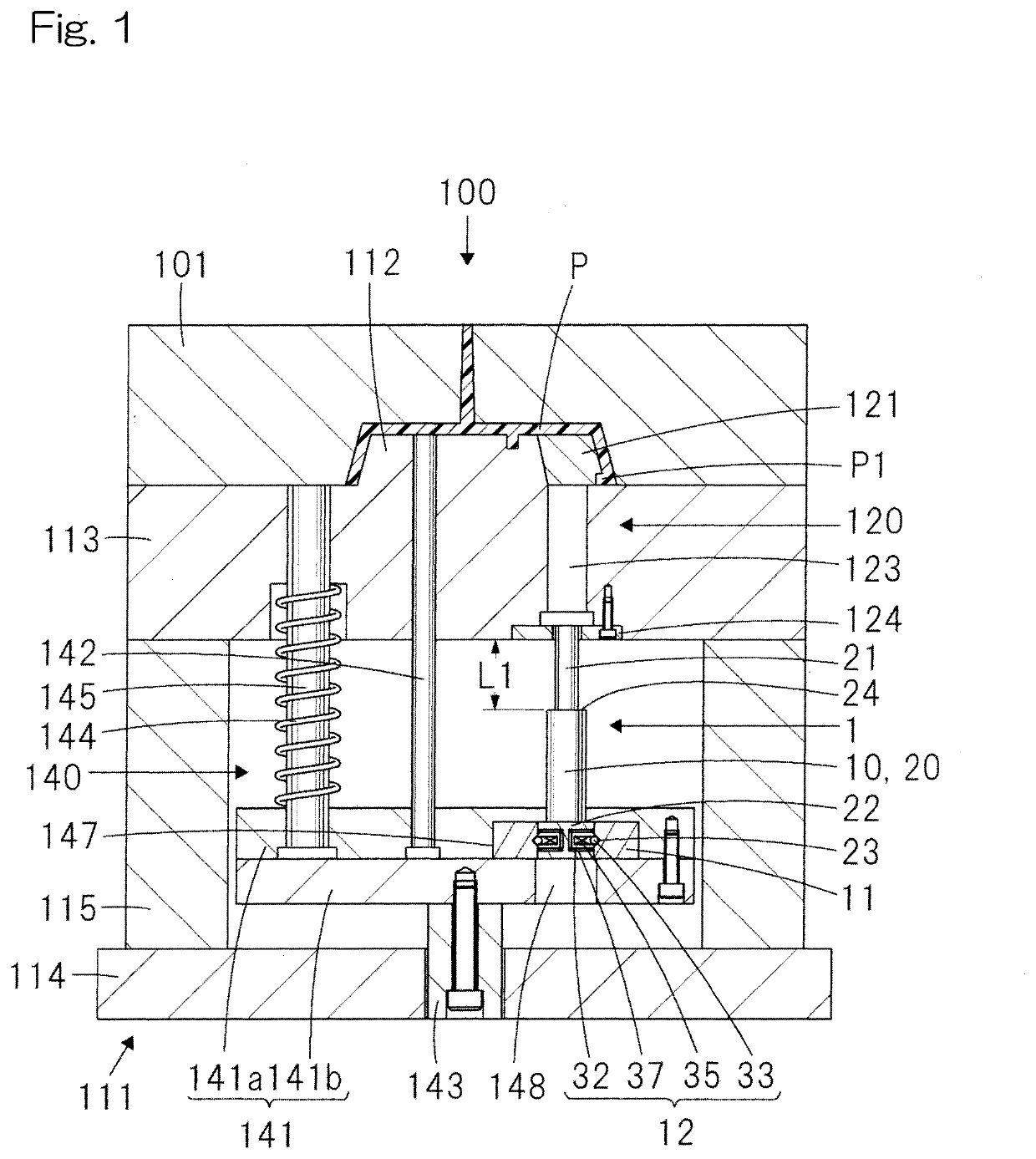
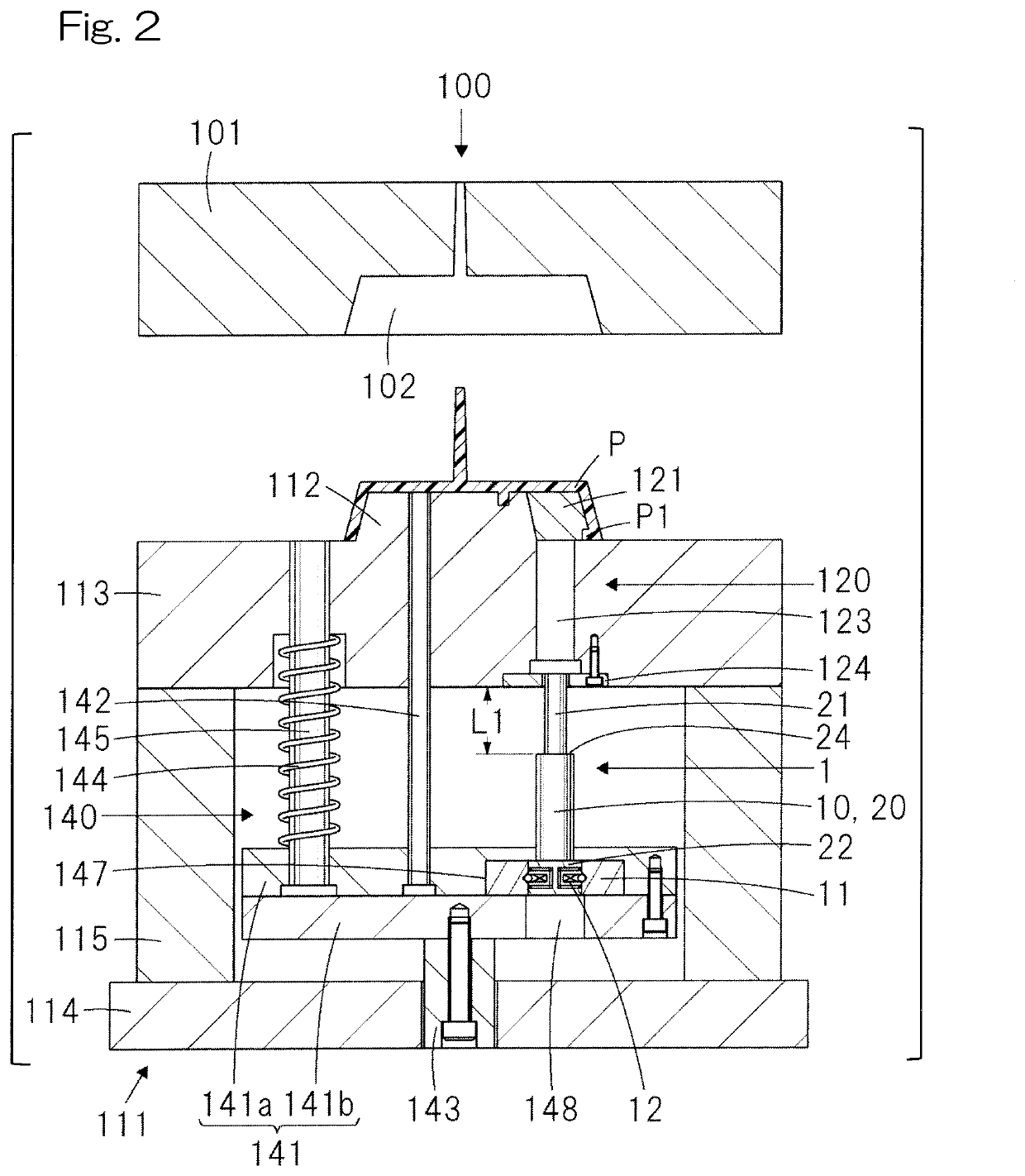
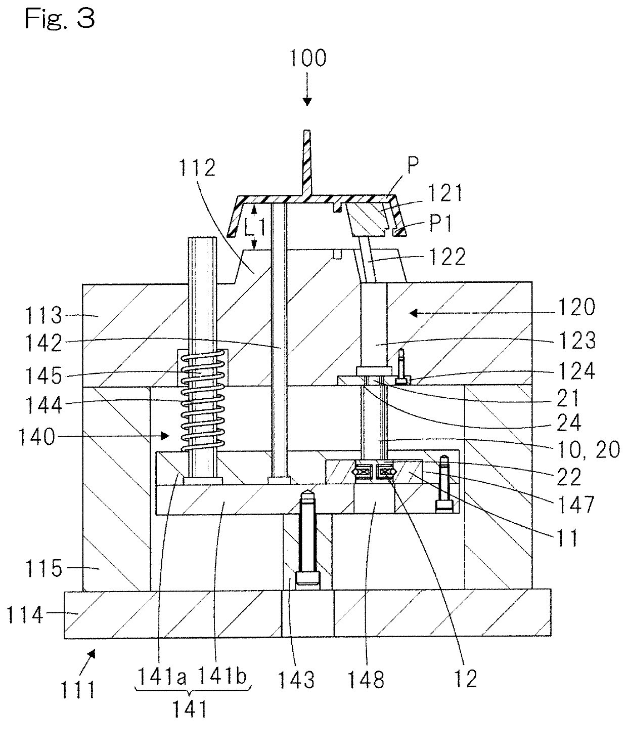
[0046]FIG. 1 is a sectional view of a main part of an injection mold 100 including a retaining unit 1 according to the present invention, at the time of mold clamping. FIG. 2 is a sectional view of a main part of the injection mold 100 shown in FIG. 1 after mold opening. FIG. 3 is a sectional view of a main part of the injection mold 100 shown in FIG. 1 after ejection operation in a first stage. FIG. 4 is a sectional view of a main part of the injection mold 100 shown in FIG. 1 after ejection operation in a second stage. FIG. 5A and FIG. 5B are sectional views of a main part of the injection mold 100 shown in FIG. 1, in which a stopper 13 for the retaining unit 1 is added. In FIG. 3 and FIG. 4, a fixed-side die 101 is not shown.

[0047]The injection mold 100 includes the fixed-side die 101 having a cavity 102 forming a molding surface, and a movable-side die 111 having a core 112 forming a molding surface, and molds a molded product P. The retaining unit 1 according to the first embod...

second embodiment

[0094]The retaining unit 3 of the present embodiment is the same as the retaining unit 2 of the second embodiment except that an ejector pin 60 does not have a step portion 24. The retaining unit 3 of the present embodiment performs abutting on the fixation plate 124 and attraction thereto, using a spring receiver 52.

[0095]In the injection mold 300 shown in the present embodiment, the compression coil spring 14 is attached to the movable-side attachment plate 114. However, in the injection mold 300 shown in the present embodiment, a guide pin 401 for the compression coil spring 14 is provided instead of the stopper 13, and the guide pin 401 does not directly push the ejector pin 60.

[0096]Operation of the injection mold 300 including the retaining unit 3 of the present embodiment at the time of ejecting a molded product, and actions of the ejection mechanism 140 and the retaining unit 3, will be described.

[0097]Hereinafter, for convenience sake, the compression coil spring 51 on the ...

third embodiment

[0108]A compression coil spring 75 is housed in the inner holder 72, and the compression coil spring 75 has both functions of the upper spring 51 and the lower spring 14 of the A guide pin 76 for the compression coil spring 75 is provided to the ejector pin 10 so as to stand from the bottom surface of the fixing member 22.

[0109]In the retaining unit 4 of the present embodiment, the bottom surface of the inner holder 72 and the bottom surface of the fixing member 22 attached to the lower end of the ejector pin 10 serve as pressure receiving surfaces against the compression coil spring 75, the compression coil spring 75 energizes the fixing member 22 upward, thereby maintaining the ejection force of the ejector pin 10, and the inner holder 72 slides in the center axis direction on the outer holder 71 in accordance with extension / contraction of the compression coil spring 75, whereby the holder 70 extends or contracts as a whole.

[0110]Since a force of the compression coil spring 75 ac...


PUM

PropertyMeasurementUnit
Forceaaaaaaaaaa
Diameteraaaaaaaaaa

Abstract

A retaining unit includes: a movable ejector pin; a ring-shaped member used in a fixed state; and a ball plunger directly attached to the ejector pin or fixed to a fixing member attached to the ejector pin. The ball plunger is configured to press the ring-shaped member and engage the ejector pin with the ring-shaped member. When a force at a predetermined level or higher is applied to the ejector pin in a movement direction of the ejector pin, the engagement with the ring-shaped member is released so that the ejector pin is allowed to move. The ball plunger is incorporated into the ejector pin or the fixing member so as to be unitized together.

Description

CROSS REFERENCE TO THE RELATED APPLICATION[0001]This application is a continuation application, under 35 U.S.C. §111(a) of international patent application No. PCT / JP2018 / 038369, filed Oct. 15, 2018, the entire disclosure of which is herein incorporated by reference as a part of this application.BACKGROUND OF THE INVENTIONField of the Invention[0002]The present invention relates to a retaining unit, an ejection mechanism of a forming mold including such a retaining unit, a fixed-side die, a movable-side die, a forming mold, and a molded product.Description of Related Art[0003]An injection mold having a two-stage ejection mechanism has been known. A conventional two-stage ejection mechanism has been known in which: first and second ejector pins are attached to first and second ejector plates, respectively; a molded product is ejected by the first ejector pin; thereafter, the second ejector plate is pushed up by the first ejector plate; and the molded product is ejected by the second ...

Claims


Application Information

Patent Timeline
IPC IPC(8): B29C45/44
CPCB29C45/44B29C33/44B29C45/4005B29C45/4435
Inventor SORIMOTO, MASANORI
Owner TECHNOCRATS CORP
Why Eureka
Try Eureka