
Floor Covering Apparatus

a floor covering and floor technology, applied in the field of modular solutions for floor coverings, can solve the problems of ineffective handling or direct multi-directional traffic, and achieve the effect of effective directing multi-directional traffic and easily replacing component parts

Inactive Publication Date: 2020-04-23
AXIS HOUSE HLDG LTD
View PDF0 Cites 0 Cited by
  • Summary
  • Abstract
  • Description
  • Claims
  • Application Information

AI Technical Summary

Benefits of technology

The present invention provides a rigid floor covering apparatus that can be used in a modular fashion, allowing for multiple design permutations. This opens up a potential for creativity in design for entrances and provides a durable and quality solution. The apparatuses can tessellate and be fitted together in an infinite number of design permutations. Additionally, the invention provides a heavy-duty, robust entrance mat solution that allows for real creativity in design and easily replaceable component parts.

Problems solved by technology

Most current rigid entrance matting is linear in construction and is not provided in multiple shapes and tessellating patterns, and therefore cannot effectively handle or direct multidirectional traffic while remaining robust to wear and tear.

Method used


Image

  • Floor Covering Apparatus
  • Floor Covering Apparatus
  • Floor Covering Apparatus

Examples


Embodiment Construction

[0043]While the present invention has been illustrated by description of several embodiments and while the illustrative embodiments have been described in detail, it is not the intention of the applicant to restrict or in any way limit the scope of the appended claims to such detail. Additional modifications will readily appear to those skilled in the art. The invention in its broader aspects is therefore not limited to the specific details, representative apparatus and methods, and illustrative examples shown and described. Accordingly, departures may be made from such details without departing from the spirit or scope of applicant's general inventive concept.

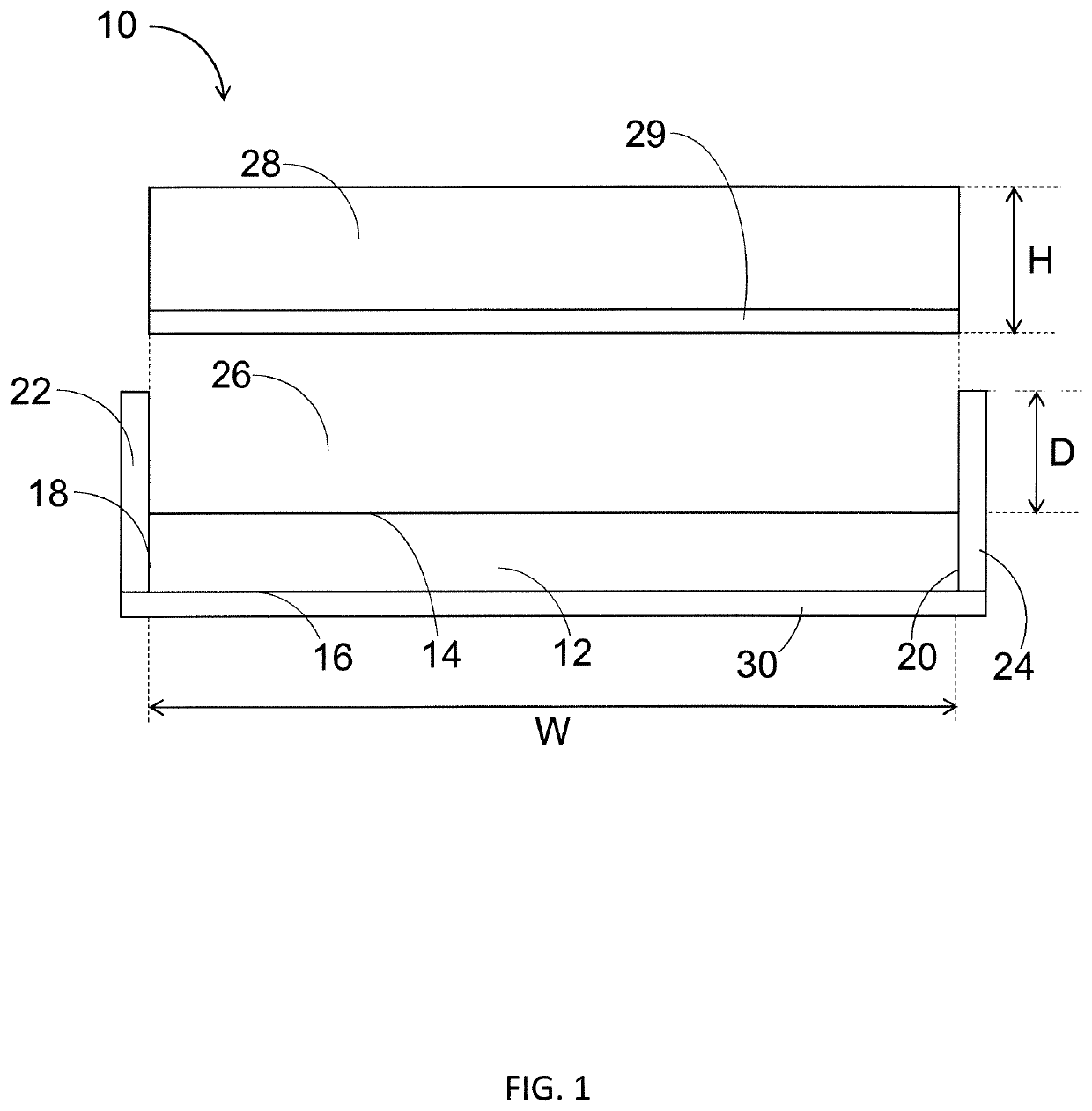
[0044]Referring to FIG. 1, an example embodiment 10 of a floor covering apparatus is shown according to the first aspect of the present invention. The floor covering apparatus 10 comprises a planar aluminium-composite base 12 having an upper face 14, a lower face 16, and a first edge 18 and a second edge 20. The floor covering...


PUM

PropertyMeasurementUnit
Shapeaaaaaaaaaa
Depthaaaaaaaaaa
Heightaaaaaaaaaa

Abstract

A floor covering apparatus is provided to enable the easy laying, relaying and rearranging of a protective floor covering while providing for improved customization. The apparatus comprises a rigid, substantially planar base having an upper face, a lower face, and a perimeter defining a two-dimensional shape; a rigid edge portion extending from the upper face of the base and defining a depth, wherein the depth is a distance between the upper face of the base and an uppermost surface of the edge portion; wherein the floor covering apparatus is arranged to tessellate with at least one other such floor covering apparatus. The apparatus aims to provide a modular floor covering apparatus with improved structural and functional properties compared with currently available solutions.

Description

CROSS-REFERENCE TO RELATED APPLICATIONS[0001]This application is a continuation of prior-filed Great Britain Application No. GB 1815624.0, filed on Sep. 25, 2018 and incorporated herein in its entirety by reference.STATEMENT REGARDING FEDERALLY-SPONSORED RESEARCH OR DEVELOPMENT[0002]Not ApplicableBACKGROUND OF THE INVENTION1. Field of Invention[0003]The present invention relates to modular solutions for covering floors, and in particular to modular entrance matting.2. Description of the Related Art[0004]Entrance matting is known and has been used for a number of years. Such entrance matting is commonly made from a woven, wear-resistant, coarse plant fibre material, such as for example, coconut fibre.[0005]A woven structure typically provides a base upon which an array of bristles pointing upwards may be located. Such bristles typically can perform the task of removing dirt and excess moisture from the underside of shoe soles. Dirt and moisture removed in this way typically falls bet...

Claims


Application Information

Patent Timeline
IPC IPC(8): E04F15/10E04F15/06
CPCE04F15/107E04F15/06E04F15/105A47L23/266A47G27/0293A47G27/0431A47G27/025
Inventor FARRANT, JAMESFARRANT, ROBERT DAVID
Owner AXIS HOUSE HLDG LTD
Learn More