Methods and apparatuses for tone mapping and inverse tone mapping

a technology of inverse tone mapping and tone mapping, which is applied in the field of can solve the problems of inefficiency of known tone mapping and inverse tone mapping techniques, and produce a low quality of experience for the viewer of images displayed on the display devi

Active Publication Date: 2020-04-23
THE UNIV OF BRITISH COLUMBIA
View PDF0 Cites 3 Cited by
  • Summary
  • Abstract
  • Description
  • Claims
  • Application Information

AI Technical Summary

Benefits of technology

[0036]In some embodiments, identifying the mapping function comprises maximizing a perceptually scaled contrast difference between the plurality of input luminance values and the plurality of output luminance values.
[0037]In some embodiments, identifying the mapping function comprises maximizing a perceptually scaled brightness difference between the plurality of input luminance values and the plurali

Problems solved by technology

However, some known tone mapping and inverse tone mapping techniques may be inefficient.
Further, some known tone mapping and inverse tone mapping techniques may introduce or aggravate visual artifacts such as visual noise, ghosting

Method used


Image

  • Methods and apparatuses for tone mapping and inverse tone mapping
  • Methods and apparatuses for tone mapping and inverse tone mapping
  • Methods and apparatuses for tone mapping and inverse tone mapping

Examples


Embodiment Construction

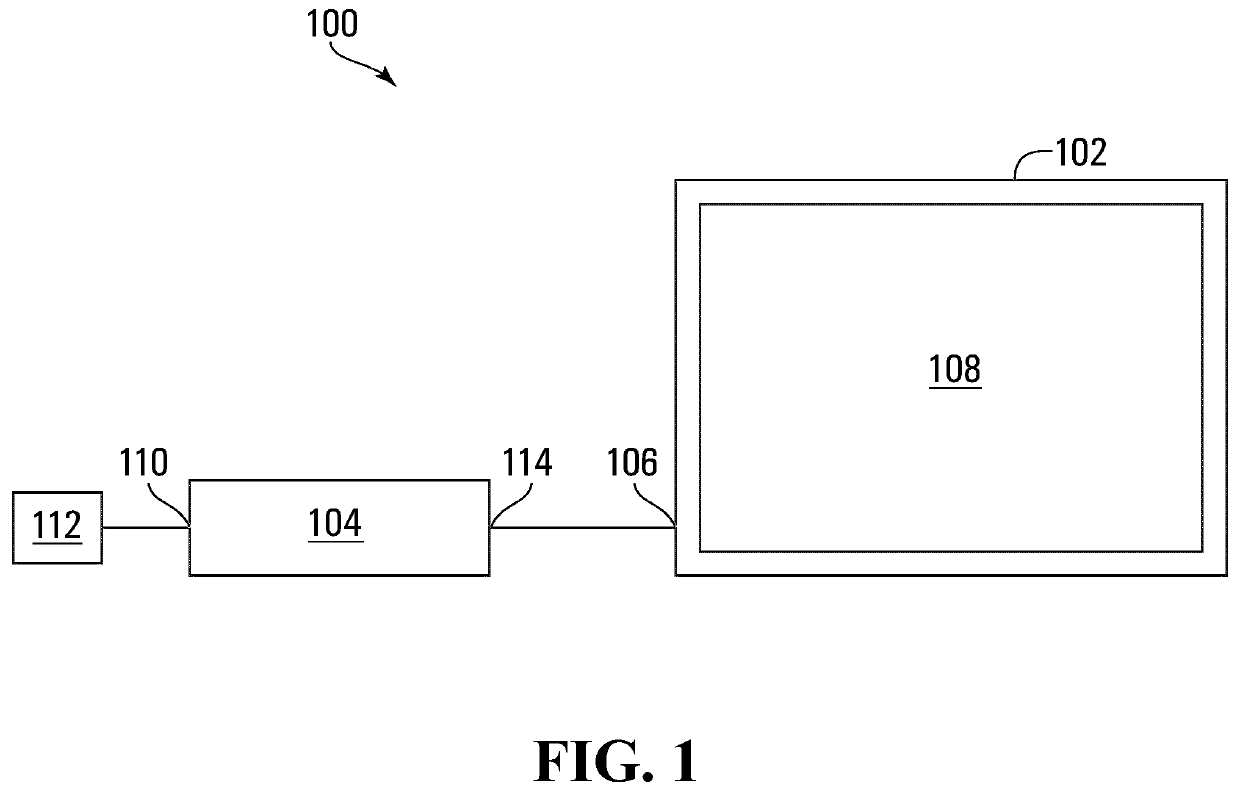
[0083]Referring to FIG. 1, a display system according to one embodiment is shown generally at 100 and includes a display device 102 and a set-top box 104. In the embodiment shown, the display device 102 is a television including an input signal interface 106 and a display screen 108. In general, the display device 102 is configured to cause the display screen 108 to display images according to input signals received at the input signal interface 106. However, alternative embodiments may vary. For example, alternative embodiments may include one or more display devices that may differ from the display device 102 and that may include a projector, for example. Further, although the display device 102 and the set-top box 104 are separate devices in the embodiment shown, alternative embodiments may vary. For example, in alternative embodiments, the display device 102 and the set-top box 104 may be integrated into one device, or alternative embodiments may include one, two, or more than t...


PUM


Abstract

A method of producing at least one output image signal representing, at least, a plurality of output luminance values in an output range of luminance values is disclosed. The method involves: identifying a mapping function based at least in part on a perceptually scaled distribution of a plurality of input luminance values in an input range of luminance values different from the output range of luminance values; transforming the plurality of input luminance values into respective perceptually scaled output luminance values according to the mapping function; transforming the perceptually scaled output luminance values into respective ones of the plurality of output luminance values; and producing the at least one output signal representing, at least, the plurality of output luminance values. Computer-readable media and apparatuses are also disclosed.

Description

CROSS-REFERENCE TO RELATED APPLICATIONS[0001]This application claims the benefit of, and priority to, U.S. provisional patent application No. 62 / 525,910 filed on Jun. 28, 2017 and U.S. provisional patent application No. 62 / 665,959 filed on May 2, 2018. The entire contents of U.S. provisional patent application Nos. 62 / 525,910 and 62 / 665,959 are incorporated by reference herein.FIELD[0002]This disclosure relates generally to tone mapping and inverse tone mapping.RELATED ART[0003]In general, a display device may receive one or more input signals and may display images, such as successive frames of video, for example, according to the one or more input signals. Different display devices are capable of displaying images in different ranges. For example, a standard dynamic range (“SDR”) may include luminance and color ranges that are less than luminance and color ranges of a high dynamic range (“HDR”). For example, HDR luminance values may range over about six orders of magnitude, wherea...

Claims


Application Information

Patent Timeline
IPC IPC(8): G09G5/02G09G5/10
CPCG09G5/02G09G5/10G09G2320/0673G09G2340/0428G09G2340/06H04N19/117H04N19/124H04N19/142H04N19/186
Inventor NASIOPOULOS, PANOSPLOUMIS, STYLIANOSTALEBPOURAZAD, MAHSABOITARD, RONANMOHAMMADI, PEDRAM
Owner THE UNIV OF BRITISH COLUMBIA
Why Eureka
Try Eureka