Reciprocating Filing Tool

a filing tool and tool holder technology, applied in the field of filing tools, can solve the problems of wasting time and effort, affecting the use of tools, so as to improve the leverage and the ability to control the tool

Inactive Publication Date: 2020-04-30
KEMP JOE
View PDF0 Cites 0 Cited by
  • Summary
  • Abstract
  • Description
  • Claims
  • Application Information

AI Technical Summary

Benefits of technology

[0008]In another embodiment, a variable control is disposed on the handle, wherein the variable control alters the rate of reciprocation generated by the motor when actuated, allowing a user to adjust the rate of filing for various tasks. In some embodiments, a stabilization platform extends from the first end, wherein the stabilization platform includes a cutout therein such that the file extends therethrough. The stabilization platform allows a user to brace the filing tool against the work surface to prevent the reciprocating motion from shifting the tool in an undesired direction. In some embodiments, the stabilization platform is arcuate, allowing a user to angle the file while braced against the work surface.
[0009]In some embodiments, the shaft is colinear with the handle, such that forces generated by the reciprocating motion of the shaft are transferred directly into the handle allowing a user to more readily control the tool without the aid of external bracing. In another embodiment, the shaft is offset from the handle, such that the user can provide increased leverage against the reciprocating movement of the shaft.

Problems solved by technology

Unfortunately, due to the intricate and irregular nature of chainsaw chains, many users must instead replace the chain when it becomes dull, which can be costly.
Alternatively, manual filing may be an option, however such filing requires a great deal of time and effort to ensure that the entire chain is properly sharpened.
This process can be time consuming and frustrating for the user.
Traditional automatic sharpening options, such as grinders, while faster than manual filing, wear away excess material from the chain, forcing the user to replace each chain more frequently.

Method used


Image

  • Reciprocating Filing Tool
  • Reciprocating Filing Tool
  • Reciprocating Filing Tool

Examples


Embodiment Construction

[0016]Reference is made herein to the attached drawings. Like reference numerals are used throughout the drawings to depict like or similar elements of the reciprocating filing tool. The figures are intended for representative purposes only and should not be considered to be limiting in any respect.

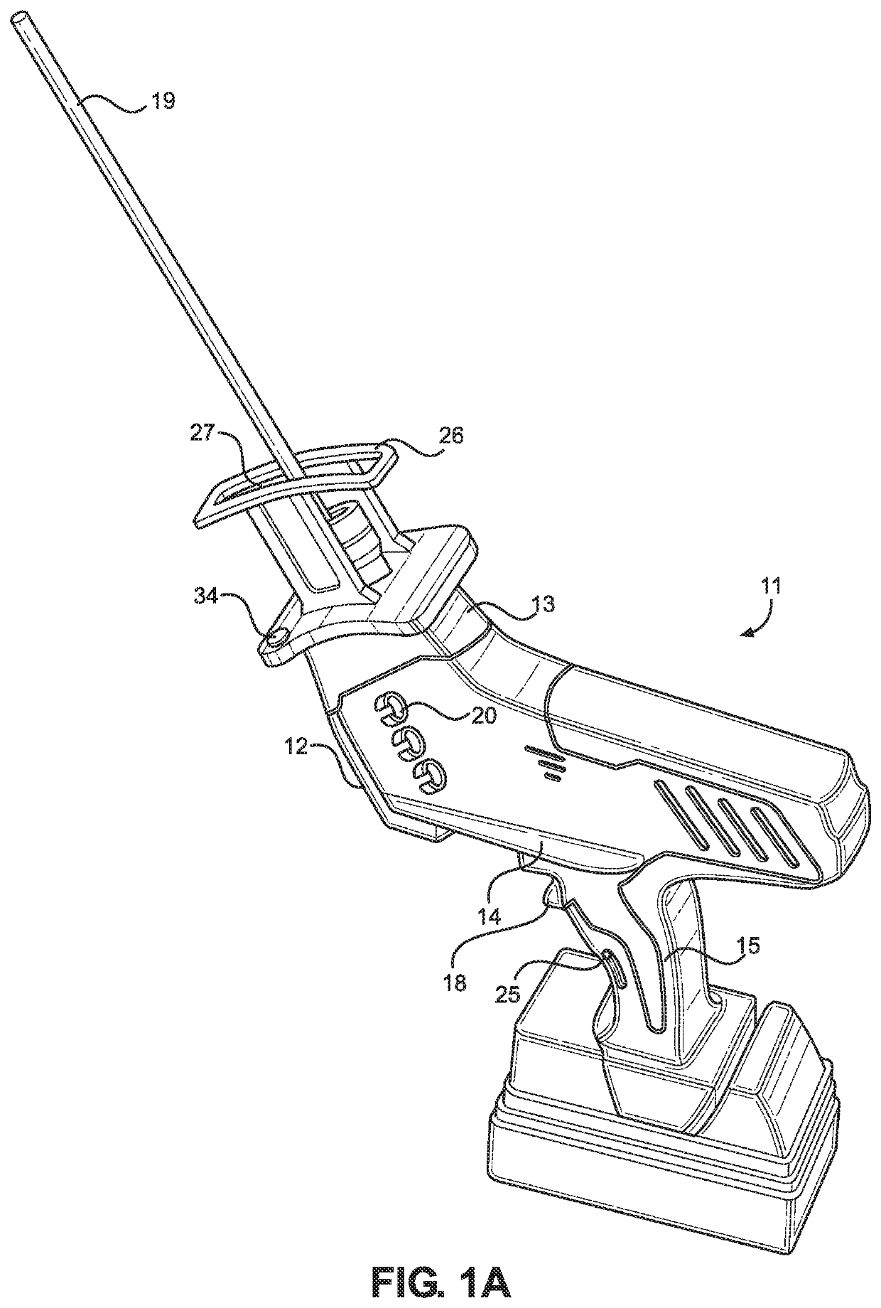
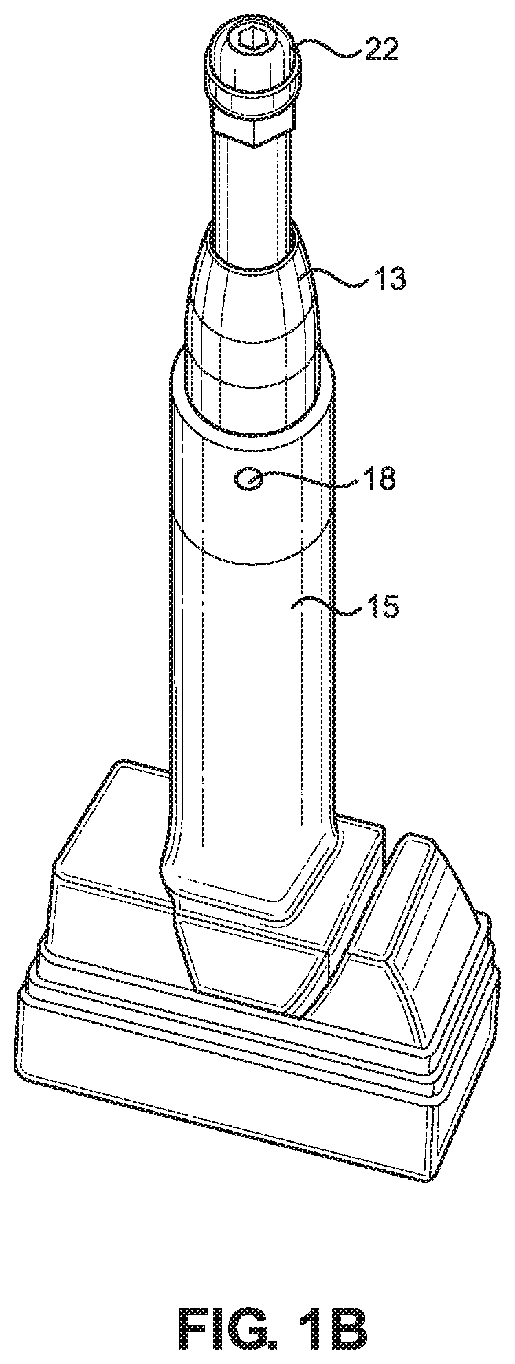
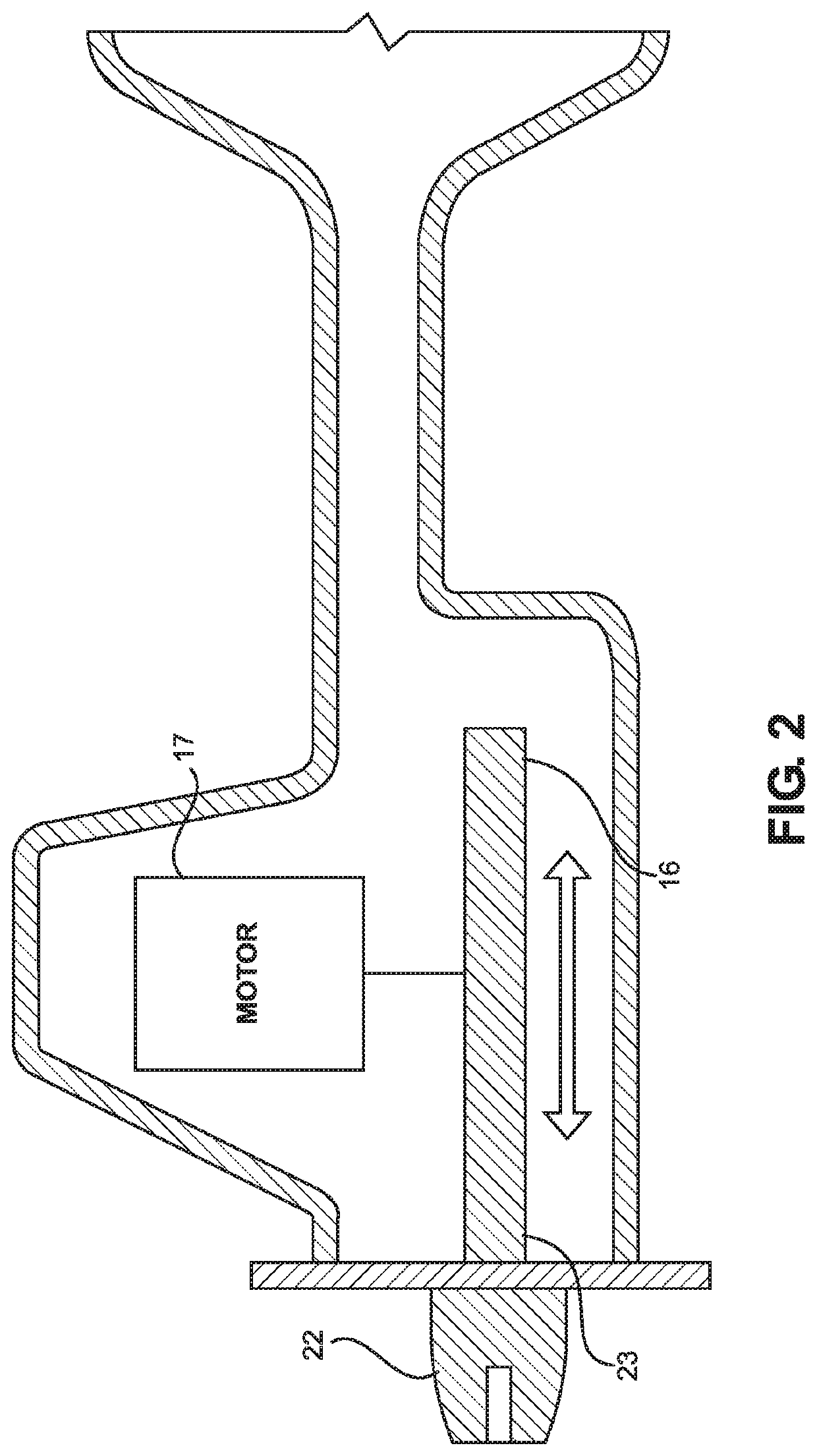
[0017]Referring now to FIGS. 1A and 1B, there are shown perspective views of various embodiments of the reciprocating filing tool. The reciprocating filing tool 11 comprises a housing 12 having a first end 13 opposite a second end 14, wherein a handle 15 extends from the second end 14. A shaft (as shown in FIG. 2, 16) is slidably disposed through the first end 13, wherein the shaft is configured to move in a reciprocating linear motion when the reciprocating filing tool 11 is in use. A file 19 is removably securable to the shaft in a coaxial relationship, such that the file 19 is driven in the same reciprocating linear motion of the shaft. In this way, the user can sharpen or otherwise fi...


PUM

PropertyMeasurementUnit
diametersaaaaaaaaaa
irregular shapesaaaaaaaaaa
timeaaaaaaaaaa

Abstract

A reciprocating filing tool. The reciprocating filing tool includes a housing having a first end opposite a second end, wherein a handle is affixed to the second end. A shaft is slidably disposed within the housing, and a motor is operably connected to the shaft. The motor causes the shaft to move in a reciprocating linear movement when the motor is activated. A trigger disposed on the handle, wherein the trigger activates the motor when actuated. A plurality of files are removably securable to a distal end of the shaft. A plurality of clips are disposed on an exterior of the housing and can removably receive the plurality of files therein.

Description

CROSS REFERENCE TO RELATED APPLICATIONS[0001]This application claims the benefit of U.S. Provisional Application No. 62 / 753,243 filed on Oct. 31, 2018. The above identified patent application is herein incorporated by reference in its entirety to provide continuity of disclosure.BACKGROUND OF THE INVENTION[0002]The present invention relates to filing tools. More particularly, the present invention pertains to reciprocating filing tools having a plurality of interchangeable files.[0003]Many individuals utilize tools with irregular shapes that must be maintained or otherwise sharpened, such as the chain of a chainsaw. Unfortunately, due to the intricate and irregular nature of chainsaw chains, many users must instead replace the chain when it becomes dull, which can be costly. Alternatively, manual filing may be an option, however such filing requires a great deal of time and effort to ensure that the entire chain is properly sharpened. This process can be time consuming and frustrati...

Claims


Application Information

Patent Timeline
Patent Type & Authority Applications(United States)
IPC IPC(8): B23D71/02B23D71/08B23D67/04B23D67/12
CPCB23D71/02B23D67/04B23D71/08B23D67/12B23D63/162B23D71/06
Inventor KEMP, JOE
Owner KEMP JOE
Why Eureka
Try Eureka