Ball valve apparatus

a ball valve and apparatus technology, applied in the direction of valve housings, valve operating means/release devices, transportation and packaging, etc., can solve the problems of non-linear overlap between the bore and the inlet and outlet with respect to the degree of rotation of the valve stein, and the inability to precisely control the flow through the ball valve. achieve the effect of improving the linearity of fluid flow

Active Publication Date: 2019-05-14
JOHNSON ELECTRIC SA
View PDF9 Cites 0 Cited by
  • Summary
  • Abstract
  • Description
  • Claims
  • Application Information

AI Technical Summary

Benefits of technology

[0007]By providing a valve ball having apertures in which the bridging element at least in part blocks the fluid flow through one or more apertures, the rate of fluid flow through the valve ball can be altered. The shape of the bridging element may be carefully selected to increase a linearity in the relationship between the angular position of the valve ball and the fluid flow through the apparatus, advantageously increasing the accuracy with which fluid flow through the apparatus can be controlled.
[0026]According to a fifth aspect of the invention, there is provided a method of improving the linearity of fluid flow through a ball valve apparatus, the method comprising the steps of: a] providing a ball valve apparatus preferably in accordance with the first and / or second aspects of the invention; and b] rotating the valve ball to increase a fluid flow across the fluid flow path, such that due to the bridging element the change in fluid flow is linearly or substantially linearly proportional to the degree of rotation of the valve ball.

Problems solved by technology

Unfortunately, the nature of the rotation of the valve ball is such that the overlap between the bore and the inlet and outlet is non-linear with respect to the degree of rotation of the valve stein.
As such, precise control of the flow through a ball valve is not possible without downstream measurement of the flow.

Method used


Image

  • Ball valve apparatus
  • Ball valve apparatus
  • Ball valve apparatus

Examples


Embodiment Construction

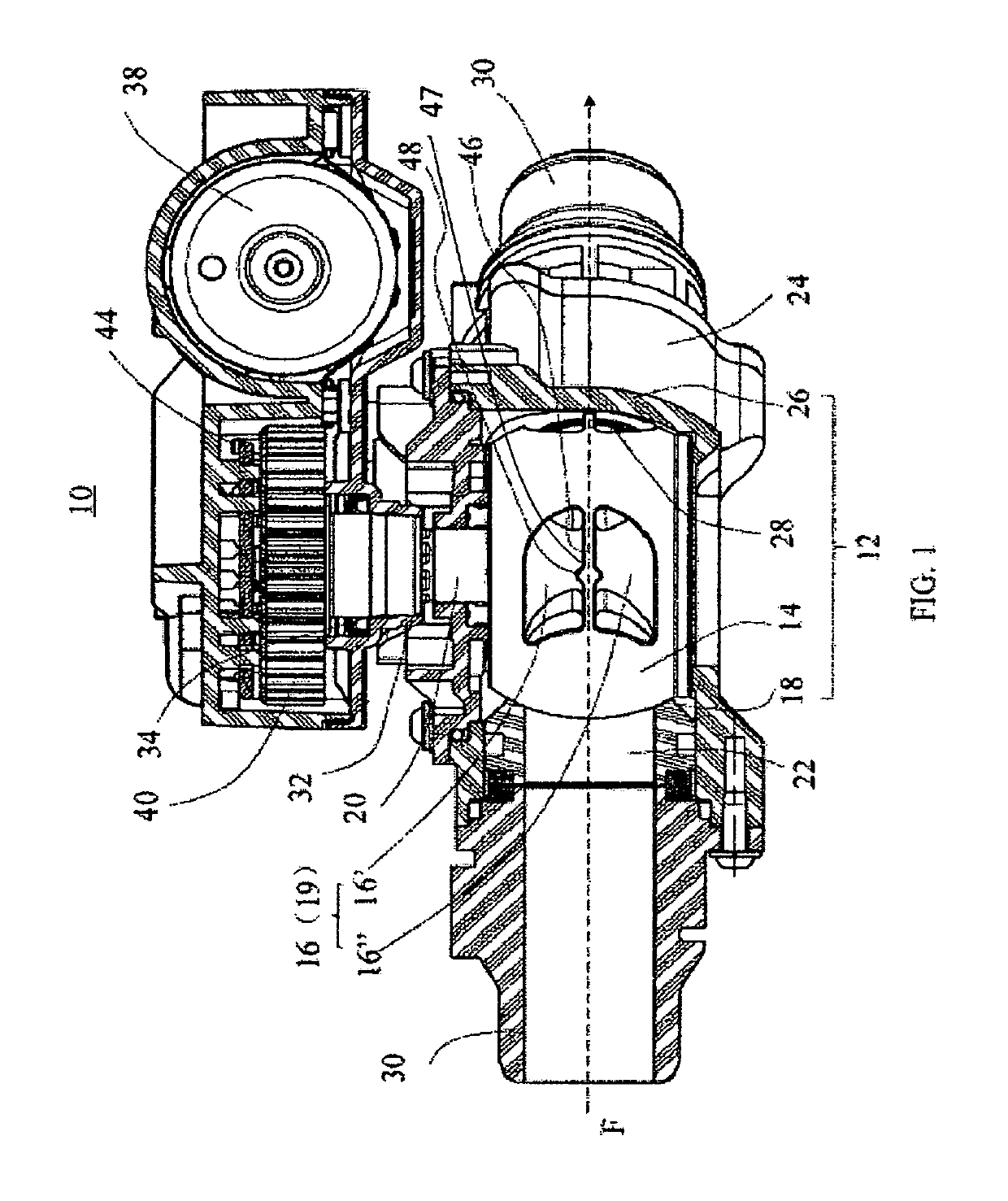
[0034]Referring to FIG. 1, there is illustrated a two-way ball valve apparatus, indicated globally at 10, and which is able to produce a linear or substantially linear flow rate through the apparatus which is proportional or substantially proportional to an actuation applied.

[0035]The ball valve apparatus 10 comprises a ball valve 12 having a valve ball 14, which has two apertures 16 therein forming ball inlet and outlets of the valve ball 14, and a valve housing 18 within which the valve ball 14 is receivable. A void, channel or bore 19 extends through the valve ball 14 to penult fluid passage therethrough. Only one of the apertures 16 is visible in FIG. 1; however, the other aperture will be positioned so as to be 180 degrees around the valve ball 14 to the illustrated aperture 16.

[0036]The valve ball 14 is engaged with a valve stem 20 via which the valve ball 14 can be rotated. The valve stem 20 may preferably be integrally formed with the valve ball 14; however, a separately eng...


PUM


Abstract

A ball valve apparatus with an improved linearity of fluid flow therethrough is provided. The ball valve includes a valve housing including a housing inlet and a housing outlet; a valve ball receivable within the valve housing, the valve ball having a bore therethrough, a ball inlet and ball outlet of the valve ball which are in fluid communication with the bore, a fluid flow path through the ball valve apparatus being defined at least in part by the housing inlet, housing outlet, ball inlet, ball outlet and the bore. There is also provided a valve stem engagable with the valve ball and. To control the fluid flow through the apparatus such that there is a linear or substantially linear relationship between at the angular position of the valve ball and the fluid flow through the apparatus, there may be provided at least one bridging element, positioned on the fluid flow path to alter a fluid flow thereacross and / or ball outlet, and / or at least one of the ball inlet and ball outlet may have a non-circular profile. A ball valve for such an apparatus is also provided, in addition to method of improving the linearity of fluid flow through a ball valve apparatus.

Description

CROSS-REFERENCE TO RELATED APPLICATIONS[0001]This non-provisional patent application claims priority under 35 U.S.C. § 119(a) from Patent Application No. 1607768.7 filed in United Kingdom on 4 May 2016.FIELD OF THE INVENTION[0002]The present invention relates to a ball valve apparatus for controlling the flow of a fluid through a system, and furthermore to a specific valve ball for use with such an apparatus. A method of improving the linearity of fluid flow through a ball valve apparatus is also provided.BACKGROUND OF THE INVENTION[0003]Valves are used to control a flow of fluid through a fluid flow apparatus, and the simplest valves are simple on-off valves which either permit or prevent fluid flow through the valve. However, more sophisticated control valves are available which are able to regulate the fluid flow through the valve in a non-binary manner.[0004]Ball valves are simple control valves; a two-way ball valve typically comprises a ball having a cylindrical bore therethro...

Claims


Application Information

Patent Timeline
Patent Type & Authority Patents(United States)
IPC IPC(8): F16K11/087F16K5/06F16K27/06F16K31/04F16K31/60F16K37/00F16K47/04
CPCF16K11/0873F16K5/0605F16K5/0647F16K27/067F16K31/602F16K37/0041F16K47/045F16K31/043Y10T137/86751F16K5/12
Inventor VUICHARD, EMMANUELBOURQUI, YVAN
Owner JOHNSON ELECTRIC SA
Why Eureka
Try Eureka