Tool and device for removal of material on surfaces

a technology for removing materials and surfaces, applied in the direction of decommissioning of buildings, ways, working accessories, etc., to achieve the effect of efficient and quick removal of the surface of the wall

Active Publication Date: 2020-04-30
ENBW ENERGIE BADEN WURTTEMBERG AG
View PDF2 Cites 0 Cited by
  • Summary
  • Abstract
  • Description
  • Claims
  • Application Information

AI Technical Summary

Benefits of technology

[0010]The object of the present invention is to provide a tool and a device, with the aid of which it is possible to efficiently and quickly remove the surface of a wall, the floor or the ceiling even in these corners.

Problems solved by technology

This means that no “leftover” remains, which would have to be laboriously removed manually or otherwise.

Method used


Image

  • Tool and device for removal of material on surfaces
  • Tool and device for removal of material on surfaces
  • Tool and device for removal of material on surfaces

Examples


Embodiment Construction

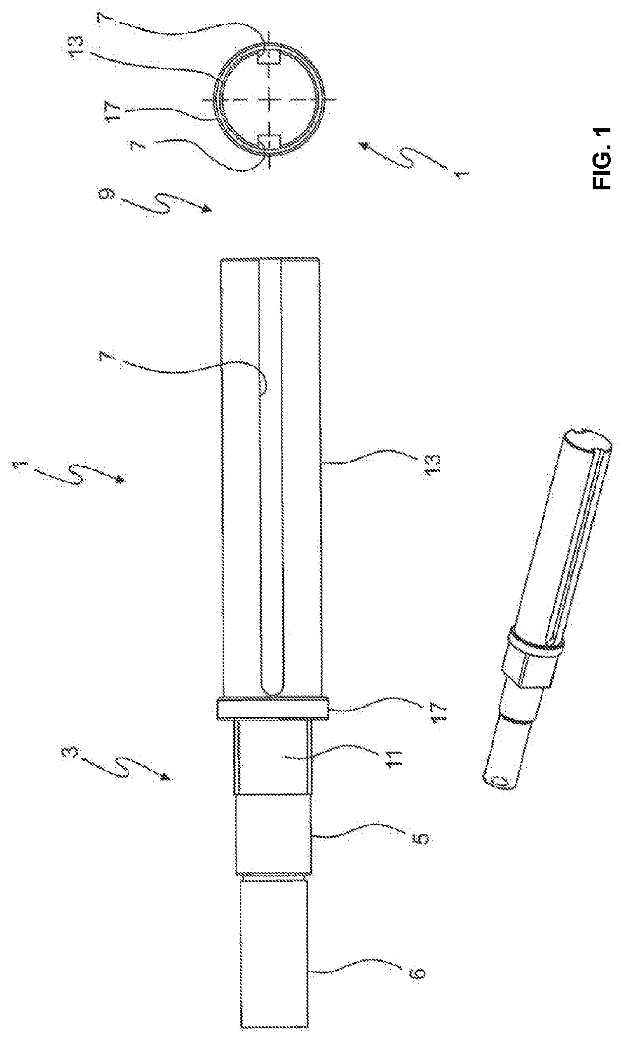
[0050]FIG. 1 shows schematically an exemplary embodiment of a drive shaft 1 according to the present invention in a side view and in a front view.

[0051]Drive shaft 1 has a first end 3. There, drive shaft 1 is rotatably mounted (not shown). The mounting can, for example, be carried out via a bearing pin 5, which is connected via a bearing block (not shown) to a sliding carriage of the device according to the present invention. There are various design options to carry out this mounting. Usually, rolling bearings are disposed between drive shaft 1 and the bearing block.

[0052]In the region of first end 3 of drive shaft 1, a stub shaft 6 is moreover provided, via which drive shaft 1 is actuated. This actuation may, for example, be via a flexible shaft (not shown), an electric motor, a hydraulic motor or any other rotary drive known from the prior art.

[0053]A plurality of saw blades (not shown in FIG. 1) can be slid onto drive shaft 1, which may have a cylindrical outer contour. The saw ...


PUM

PropertyMeasurementUnit
depthaaaaaaaaaa
lengthaaaaaaaaaa
depth of immersionaaaaaaaaaa

Abstract

The invention proposes a tool and device, with the aid of which it is possible to remove the surface of walls, ceilings and floors also in the corners of contaminated interiors.

Description

CROSS REFERENCE TO RELATED APPLICATIONS[0001]The present application is the United States National Stage Application of International Application No. PCT / EP2017 / 078077, filed Nov. 2, 2017, which claims priority to German patent application No. 10 2016 120 852.3, filed on Nov. 2, 2016, the entire contents of which each of which are incorporated herein by reference.BACKGROUND OF THE INVENTION[0002]The present invention relates to a tool and a device for the removal of contaminated material from a wall.[0003]When dismantling nuclear facilities, minimizing contaminated waste is a top priority. This also applies to an efficient decontamination of floors and walls of buildings made of concrete, which protect the nuclear facility or parts thereof from external influences.[0004]Within the context of the claimed invention, for reasons of linguistic simplification, it primarily will be talked about a wall; however, the floors and ceilings of rooms and other surfaces are always meant as well. ...

Claims


Application Information

Patent Timeline
Patent Type & Authority Applications(United States)
IPC IPC(8): B28D1/04B28D1/12
CPCB28D1/048G21D1/003B28D1/121B28D7/02B28D1/18B28D1/186B27B5/34E01C23/09
Inventor BOERSCH, FABIANDIETZ, KEVINFEIL, HARTMUTGREB, JOHANNESHAMMER, FABIAN
Owner ENBW ENERGIE BADEN WURTTEMBERG AG
Why Eureka
Try Eureka