
Method and Apparatus for Encapsulating Tubing with Material Having Engineered Weakened Portions

a technology of weakened portions and encapsulated tubing, which is applied in the field of encapsulated conduits, can solve the problems of affecting integrity, introducing imperfections in the sealing surface area of both hydraulic and electrical connectors, and damaging the encapsulated tubing

Inactive Publication Date: 2018-07-19
MID SOUTH CONTROL LINE LLC
View PDF15 Cites 2 Cited by
  • Summary
  • Abstract
  • Description
  • Claims
  • Application Information

AI Technical Summary

Benefits of technology

The invention includes an elongate central member, such as a conduit or cable, with a protective outer coating or jacket made of a polymer or thermoplastic resin. The jacket has been engineered with reduced material to create weak points, which can be torn open easily without damaging the conduit or cable. This allows for quick and efficient removal of the jacket without the need for a knife or special tool. The invention also includes a user-friendly design that allows for easy gripping and separation of the jacket from the conduit, ensuring that the conduit remains surface-free during jacket removal.

Problems solved by technology

Although functional, such existing methods incorporating the use of uncommon, specially designed tools or, blades, and / or heat to cut / strip encapsulation materials introduce significant risk of damaging the encapsulated tubing, thus adversely affecting integrity and introducing imperfections in the sealing surface area of both hydraulic and electrical connectors.
The process of peeling back the encapsulation is inherently unsafe, and much force is needed for a user to pull the cord to enable the user to carry out the task of stripping encapsulation material from the tubing.
Further, such conventional methods and tools can be hazardous, as workers can easily cut themselves with sharp knives and / or other tools, while heat sources may be dangerous to use in environments where flammable materials, such as fossil fuels, are present.
In addition, many of these conventional tools tend to damage the exterior surface of an encapsulated metallic tube, and damage can also occur to areas of encapsulation material where removal was not necessary or desired.

Method used


Image

  • Method and Apparatus for Encapsulating Tubing with Material Having Engineered Weakened Portions
  • Method and Apparatus for Encapsulating Tubing with Material Having Engineered Weakened Portions
  • Method and Apparatus for Encapsulating Tubing with Material Having Engineered Weakened Portions

Examples


Embodiment Construction

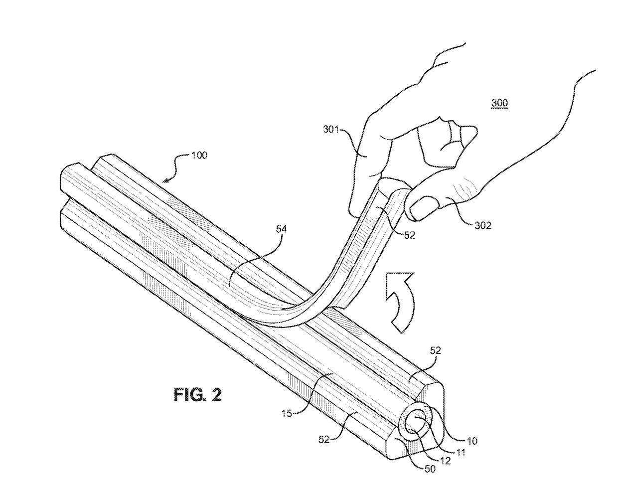
[0026]In a preferred embodiment, an encapsulated conduit assembly of the present invention comprises an elongate central member (including, without limitation, a conduit, cable or wire) having a protective outer coating or jacket. Said outer coating or jacket can comprise a polymer, thermoplastic resin and / or combination thereof, and can beneficially include at least one engineered weak point(s)—that is, at least one strategically positioned region comprising reduced jacket material. Said at least one engineered weak point(s) can be created through an extrusion process, or created through removal of extruded material in a secondary process.

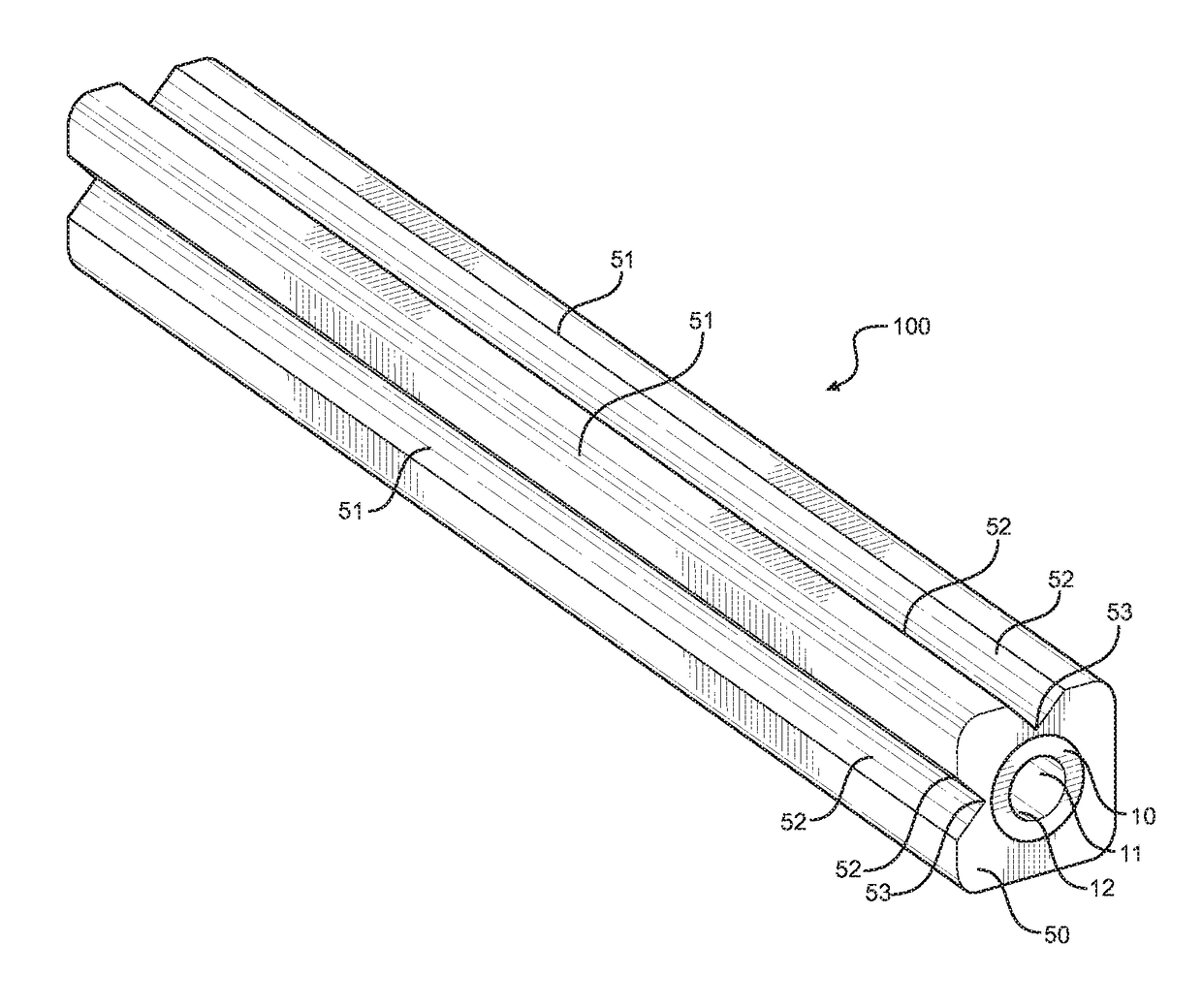
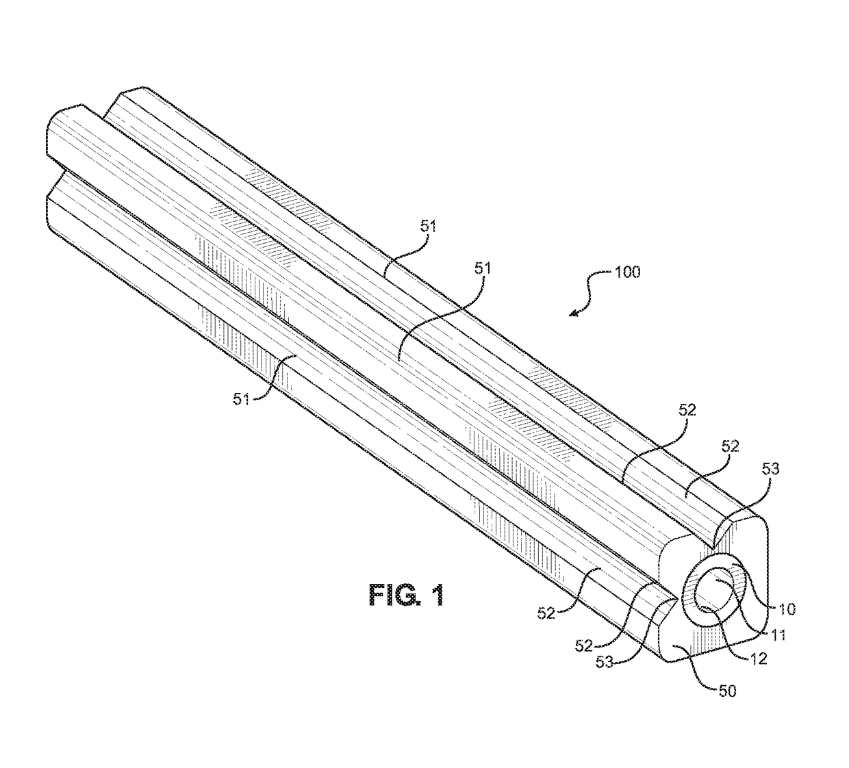
[0027]Referring to the drawings, FIG. 1 depicts a perspective view of an encapsulated conduit assembly 100 of the present invention. Said encapsulated conduit assembly 100 comprises central elongate tubular conduit 10 having central through bore 11 defining inner surface 12. Protective outer coating or jacket 50 is generally disposed around the ou...


PUM

PropertyMeasurementUnit
Thicknessaaaaaaaaaa
Areaaaaaaaaaaa
Tear strengthaaaaaaaaaa

Abstract

An elongate central member (including, without limitation, a conduit, cable or wire) has an outer coating or jacket constructed of polymer(s), thermoplastic resin(s) or other protective material. The outer coating or jacket can include at least one engineered area of reduced material, which can be created through the extrusion process or through removal of extruded material in a secondary process, thereby forming at least one intentionally weakened section of the coating or jacket. When desired, the outer coating or jacket can be partially or totally removed without damage to the encased elongate central member.

Description

CROSS REFERENCES TO RELATED APPLICATION[0001]Priority of U.S. provisional patent application Ser. No. 62 / 446,987, filed Jan. 17, 2017, incorporated herein by reference, is hereby claimed.STATEMENTS AS TO THE RIGHTS TO THE INVENTION MADE UNDER FEDERALLY SPONSORED RESEARCH AND DEVELOPMENT[0002]NoneBACKGROUND OF THE INVENTION1. Field of the Invention[0003]The present invention pertains to encapsulated conduits utilized in a variety of applications including, without limitation, in the oil and gas industry. More particularly, the present invention pertains to metallic conduits encapsulated within polymer material having engineered weak points in said polymer encapsulation material (such as, for example, predetermined areas having reduced encapsulation material). More particularly still, the present invention pertains to polymer-encapsulated metallic conduits that permit stripping and / or removal of said polymer encapsulation material from an encased conduit, typically without requiring s...

Claims


Application Information

Patent Timeline
IPC IPC(8): B29C70/86B29C43/18B32B1/08
CPCB29C70/865B29C43/18B32B1/08B29C2043/182B29C2049/2004B29C2793/0063B29C70/72B29C48/06B29C48/12B29C48/151B29C48/21B32B2307/748B32B3/30B32B2307/5825B32B2250/02B32B25/16B32B2307/732B32B3/20B32B27/285B32B15/18B32B27/34B32B27/32B32B27/322B32B2274/00B32B27/288B32B2270/00B32B7/022B32B15/088B32B15/082B32B15/085B32B15/08B32B15/06B32B2307/7145B32B3/04B32B27/28B32B2597/00B32B7/06B32B27/304B32B2307/554B29C49/20
Inventor WESTWOOD, CLIFFORD WESTLEYBAUDIER, RICHARD JOSEPHCOBERT, BLAISE JOHN
Owner MID SOUTH CONTROL LINE LLC
Learn More