
Systems and methods for printing a fiber structure

a technology of fiber structure and printing method, applied in the direction of additive manufacturing process, manufacturing tool, applying layer means, etc., can solve the problems of leading and/or trailing fibers that distort the dimensions of printed fibers and 3d structures, inaccuracy or distortion of desired 3d structures, etc., and achieve the effect of constant mass flow rate and constant mass flow ra

Active Publication Date: 2020-04-30
ASPECT BIOSYST
View PDF1 Cites 1 Cited by
  • Summary
  • Abstract
  • Description
  • Claims
  • Application Information

AI Technical Summary

Benefits of technology

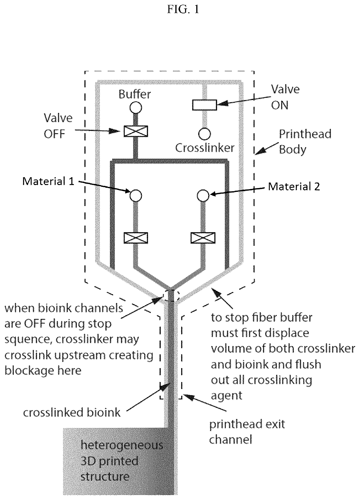
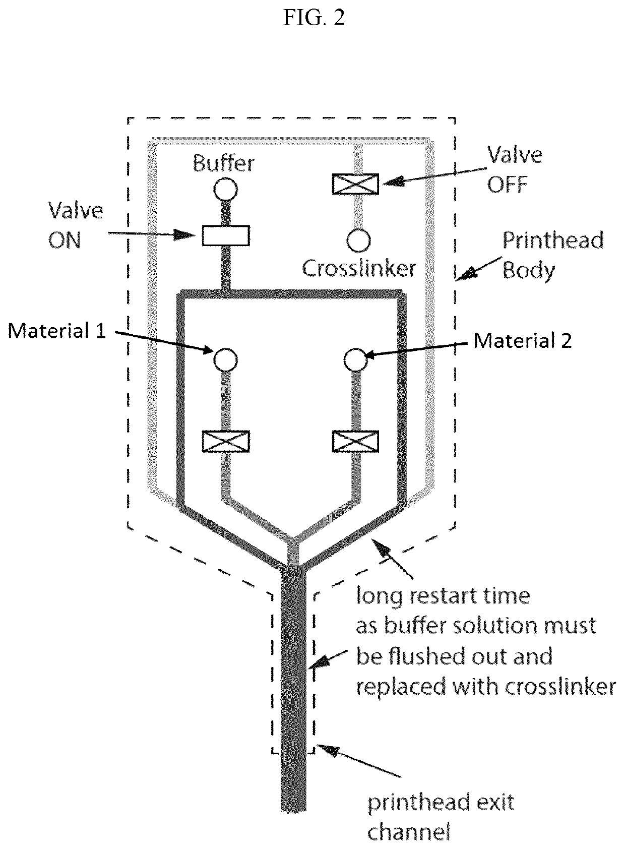
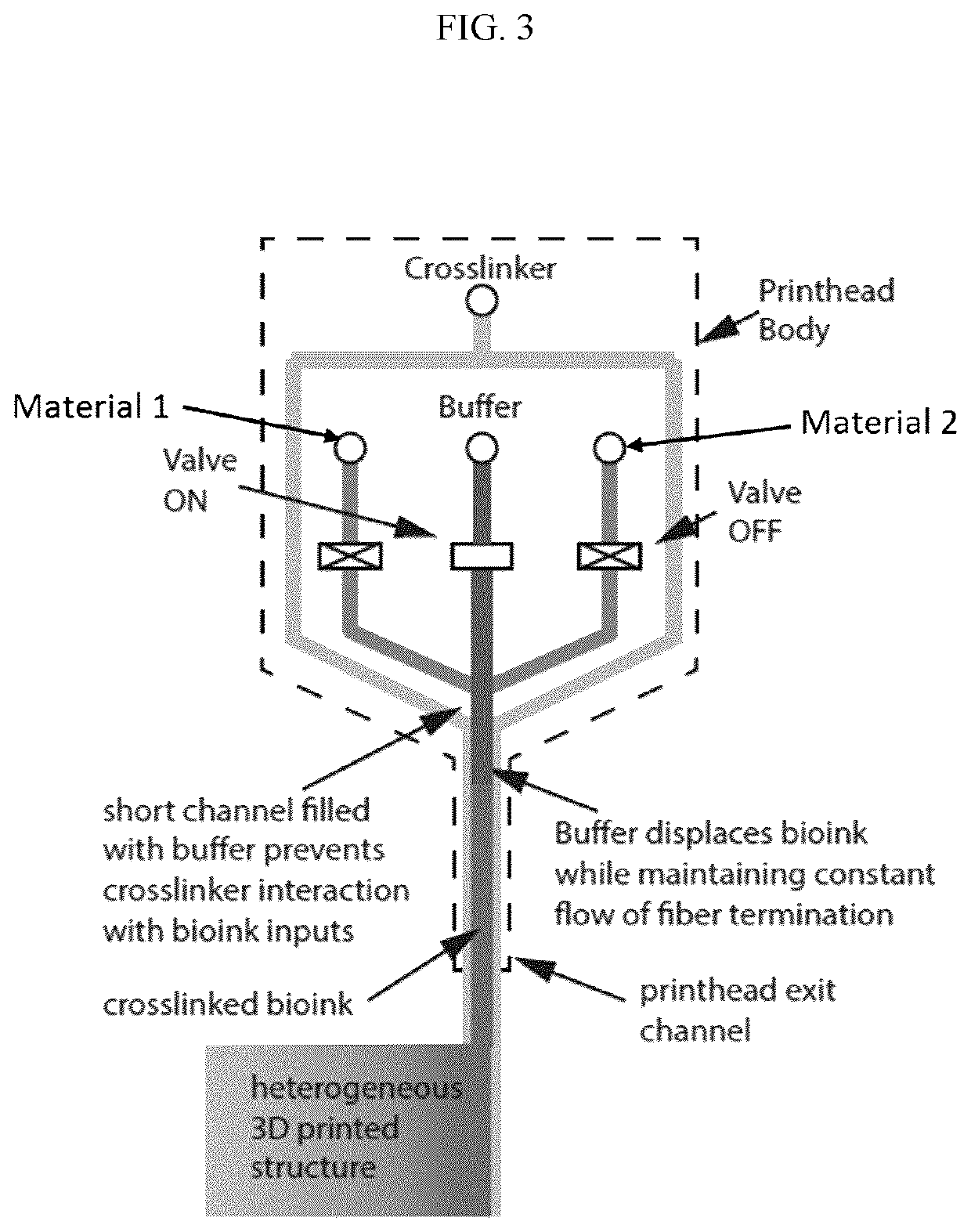
The patent describes a system for producing fiber structures and three-dimensional structures using a print head. The print head has a dispensing channel with a distal end and a proximal end, and one or more material channels that converge with the dispensing channel at the proximal end. The print head also has a buffer solution channel and a sheath solution channel that converge with the dispensing channel at the proximal end. The print head can displace input materials with a buffer solution at the proximal end of the dispensing channel. The system also includes a programmable control processor for controlling the positioning of the print head, a fluid removal component for removing excess fluid, and a pressure control component for regulating the flow rate of fluids. The system can also include one or more fluid reservoirs for supplying the input materials and a crosslinking component for solidifying the input materials. The technical effects of the patent include improved precision in producing fiber structures and three-dimensional structures using a print head.

Problems solved by technology

Unfortunately, existing systems and devices used for 3D bioprinting have suffered from various drawbacks that have resulted in inaccuracies or distortions of the desired 3D structures.
Specifically, inaccurate commencement and / or cessation of the printing process can result in the formation of leading and / or trailing fibers that distort the dimensions of printed fibers and 3D structures.

Method used


Image

  • Systems and methods for printing a fiber structure
  • Systems and methods for printing a fiber structure
  • Systems and methods for printing a fiber structure

Examples


Embodiment Construction

[0029]Aspects of the invention include systems and methods for producing fiber structures, and for producing three-dimensional (3D) structures from digital files. In some embodiments, the printed fibers comprise living cells.

Definitions:

[0030]For purposes of interpreting this specification, the following definitions will apply, and whenever appropriate, terms used in the singular will also include the plural and vice versa. In the event that any definition set forth conflicts with any document incorporated herein by reference, the definition set forth below shall control.

[0031]The term “displace” as used herein refers to the ability of a first material or fluid to remove a second material or fluid from a given position. For example, in some embodiments, a buffer solution is configured to displace an input material from a position within a dispensing channel (e.g., from a proximal end of the dispensing channel). In some embodiments, a displacement is an instantaneous displacement, wh...


PUM

PropertyMeasurementUnit
timeaaaaaaaaaa
timeaaaaaaaaaa
timeaaaaaaaaaa

Abstract

Aspects of the invention include systems and methods for producing fiber structures, and for producing three-dimensional (3D) biological structures from digital files. In some embodiments, the printed fibers comprise living cells. Aspects of the invention further include a print head for producing the fiber structure, the print head comprising: a dispensing channel comprising a distal and proximal end; a dispensing orifice located at the distal end of the dispensing channel; one or more material channels converging with the dispensing channel at its proximal end; a buffer solution channel converging with the one or more material channels at the proximal end of the dispensing channel; and a sheath solution channel converging with the dispensing channel at a position located between the proximal and distal ends of the dispensing channel. The print head is configured to displace one or more input materials with a buffer solution at the proximal end of the dispensing channel to terminate the fiber structure with a clean tail end.

Description

FIELD OF THE INVENTION[0001]The present invention relates to systems and methods for producing fiber structures, and to three-dimensional (3D) printing of structures from digital files. In some embodiments, the printed fibers comprise living cells.BACKGROUND OF THE INVENTION[0002]The tissue engineering art has long sought to fabricate viable synthetic structures capable of mimicking and / or replacing living organs and tissues using myriad materials and methods. Historically, cells and other biological materials have been seeded into pre-formed three-dimensional scaffolds imparting a desired structure, with the scaffold preferably being biodegradable or otherwise removable. See, e.g. U.S. Pat. No. 6,773,713.[0003]More recently, 3D printing, a form of additive manufacturing, has been applied to create three-dimensional objects directly from digital files, wherein the object is built up layer-by-layer to achieve the desired three dimensional structure. Initial efforts to adapt 3D printi...

Claims


Application Information

Patent Timeline
Patent Type & Authority Applications(United States)
IPC IPC(8): B29C64/209B33Y10/00B33Y30/00B33Y50/02B33Y70/00B29C64/106B29C64/336B29C64/343B29C64/393
CPCB33Y50/02B33Y30/00B29C64/393B33Y10/00B29C64/209B29L2031/7532B33Y70/00B29C64/336B29C64/343B33Y80/00B29C64/106
Inventor BEYER, SIMONMOHAMED, TAMER
Owner ASPECT BIOSYST
Learn More