Battery Powered Long-Lever Sander

Inactive Publication Date: 2020-05-14
LI TINGJIN
View PDF0 Cites 3 Cited by
  • Summary
  • Abstract
  • Description
  • Claims
  • Application Information

AI Technical Summary

Benefits of technology

[0022]The sanding disc suspending device includes a mounting base disposed on the housing. A symmetrical supporting arm extends from the tail end of the handle, and the other end of the supporting arm is connected to the mounting base. The sanding disc suspending device further includes at least one strip-like elastic piece, with two ends of the strip-like elastic piece being fixedly connected to the supporting arm. A snap-in device for fixing the strip-like elastic piece is disposed below the strip-like elastic piece. The middle portion of the strip-like elastic piece is fastened in the snap-in device, and the snap-in device is capable of hooking on to the strip-like elastic piece so as to elastically connect one side of the sander head to the supporting arm. In use, when the sanding disc comes into contact with a wall, the stressed side can be pulled down by the strip-like elastic piece so that the sanding disc remains parallel to the wall and the working center of gravity of the sander head is effectively balanced. Thus, when sanding a ceiling

Problems solved by technology

When sanding a ceiling, it needs more effort to operate due to uneven stress.
(2) An existing sander with a dust suction device may have a poor dust suction effect due to limitations of the mechanism.
Secondly, a sanding disc of the wall sander has an abrasive surface structure and is a flat surface as a whole with single structure and function.
After being used for a long time, the sanding disc may have a rubbing surface apt to be damaged by the sanding disc and may be di

Method used


Image

  • Battery Powered Long-Lever Sander
  • Battery Powered Long-Lever Sander
  • Battery Powered Long-Lever Sander

Examples


Embodiment Construction

[0028]The technical solutions in embodiments of the utility model will be described clearly and fully in combination with the accompanying drawings in the embodiments of the utility model. It is apparent that the described embodiments are merely part of, rather than all, embodiments of the utility model. Any other embodiments obtained by those of ordinary skill in the art based on the embodiments in the utility model without creative efforts shall fall into the scope of protection of the utility model.

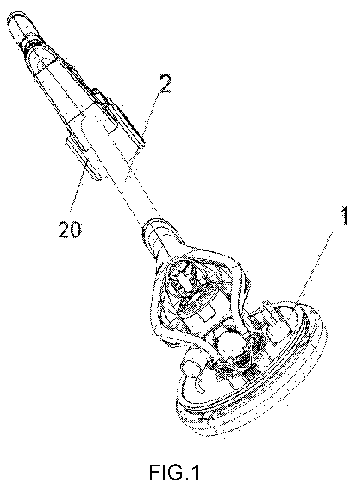
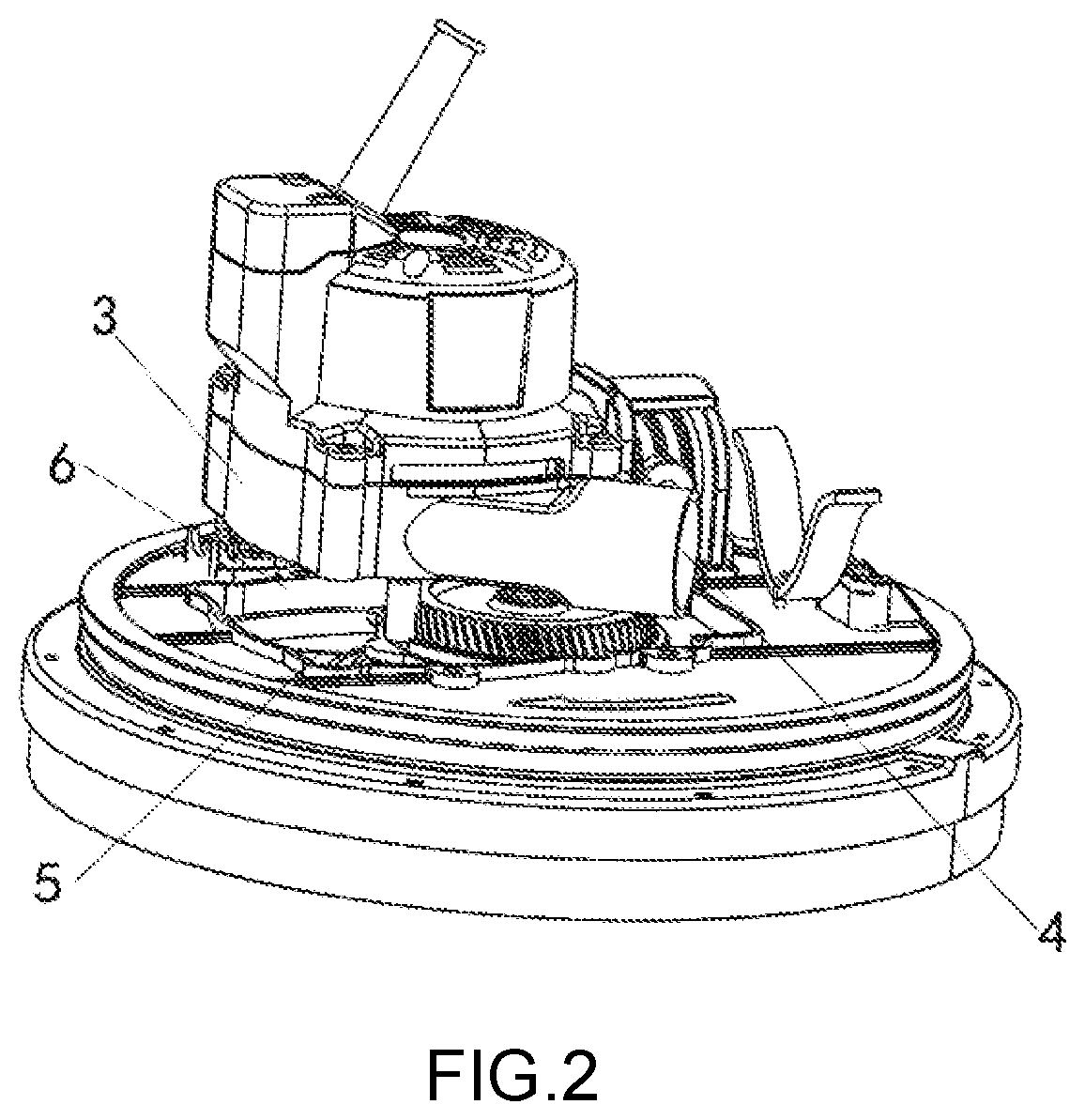
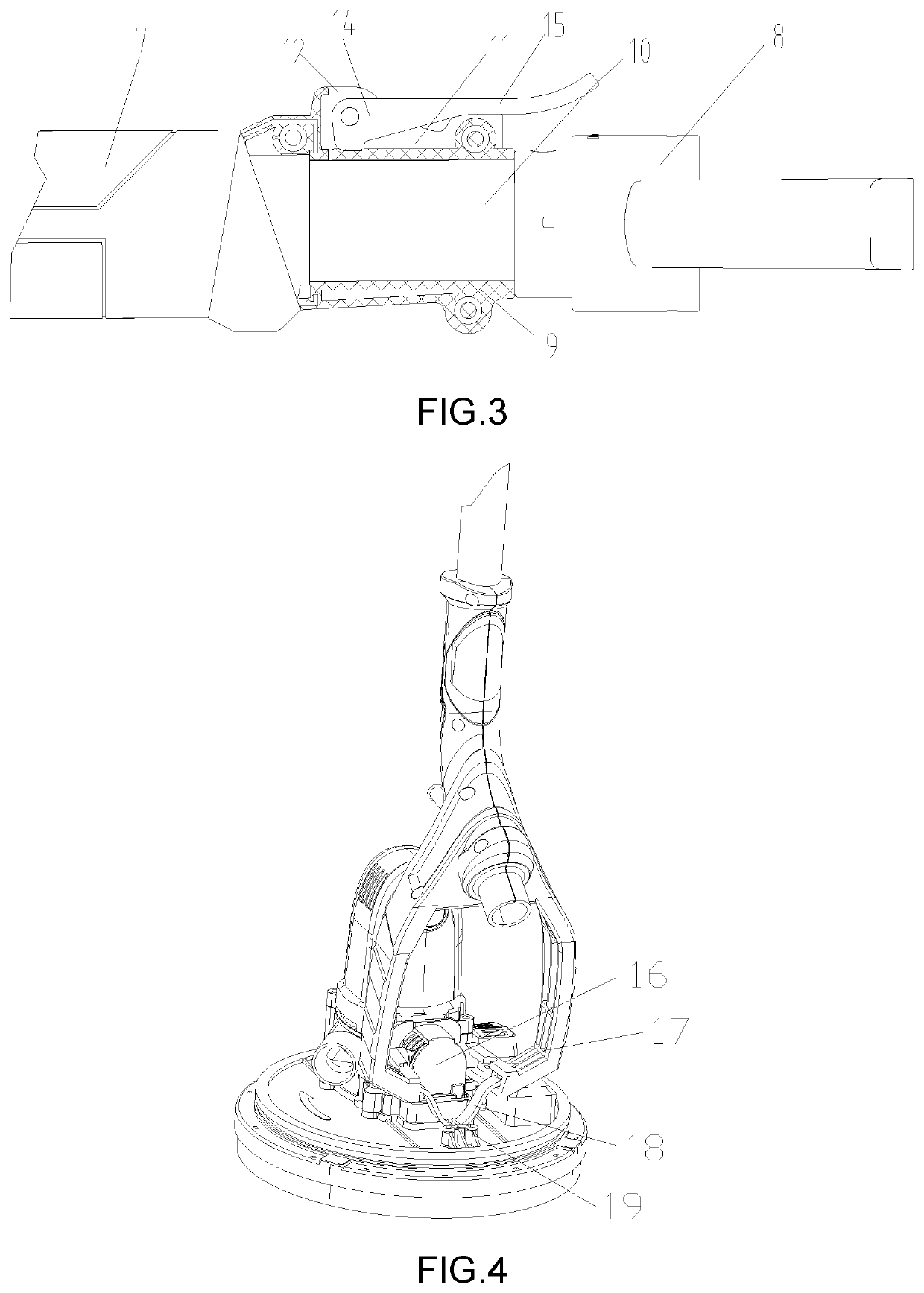
[0029]Referring to FIGS. 1-4, the utility model provides a technical solution as follows:

[0030]A battery powered long-lever sander includes a sander head assembly 1. The sander head assembly 1 includes a housing and a sanding disc disposed in the housing. The battery powered long-lever sander also includes a driving system connected to the sanding disc and configured to drive the sanding disc to run. The driving system is electrically connected to a driving power source which is a batt...


PUM


Abstract

The utility model discloses a battery powered long-lever sander. The battery powered long-lever sander includes a sander head assembly and a handle. The sander head assembly is connected to the handle and includes a housing and a sanding disc that is disposed in the housing. The battery powered long-lever sander further includes a driving system connected to the sanding disc and configured to drive the sanding disc to run. The driving system is electrically connected to a driving power source, and the driving power source is a battery pack so that the sander can be used without limitations of plugging of a power wire and thus can be used more conveniently.

Description

BACKGROUND OF THE INVENTION[0001]The utility model relates to the technical field of sanders, and more particularly to a battery powered long-lever sander.[0002]Before plastering, painting or wallpapering of a wall, the wall needs to be sanded and cleaned. As a mature technology, wall sanders have been extensively used. In the prior art, wall sanders are mostly used for sanding a wall, and there may exist some defects as follows when they are used for sanding a ceiling: (1) To facilitate omnidirectional sanding of a ceiling and a wall, a sanding disc and a handle are movably connected to each other. When sanding a ceiling, the sanding disc has only one stressed side with the ceiling, and the load-bearing side comes into contact with the ceiling while the other side of the sanding disc will drop down. When sanding a ceiling, it needs more effort to operate due to uneven stress. (2) An existing sander with a dust suction device may have a poor dust suction effect due to limitations of...

Claims


Application Information

Patent Timeline
IPC IPC(8): B24B7/18B24B47/12
CPCB24B7/184B24B47/12
Inventor LI, TINGJIN
Owner LI TINGJIN
Why Eureka
Try Eureka