Motor core

a motor core and core technology, applied in the field of motor cores, can solve the problems that the eddy current loss cannot be reduced in some cases, and achieve the effect of improving the space factor and reducing the eddy current loss

Inactive Publication Date: 2020-05-14
TOYOTA JIDOSHA KK
View PDF0 Cites 10 Cited by
  • Summary
  • Abstract
  • Description
  • Claims
  • Application Information

AI Technical Summary

Problems solved by technology

In the above-described core where the voids generated between the metal plates are used to insulate the metal plates from one another, at a peripheral edge portion of the laminated body close to fixing positions of the plurality of metal plates, the metal plates are mutually in close contact and fail to ensure sufficient insulation, thus the eddy-current loss cannot be reduced in some cases.

Method used


Image

  • Motor core
  • Motor core
  • Motor core

Examples


first embodiment

I. First Embodiment

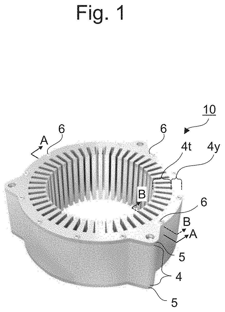
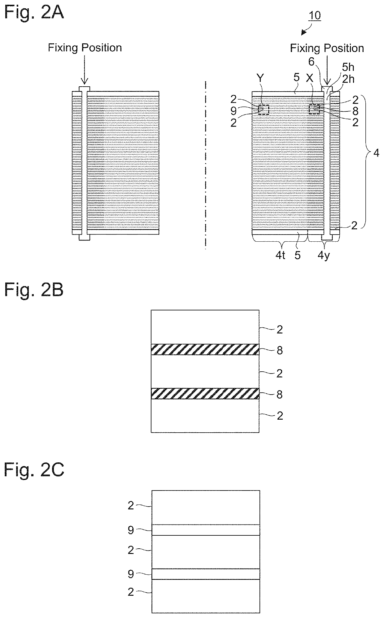
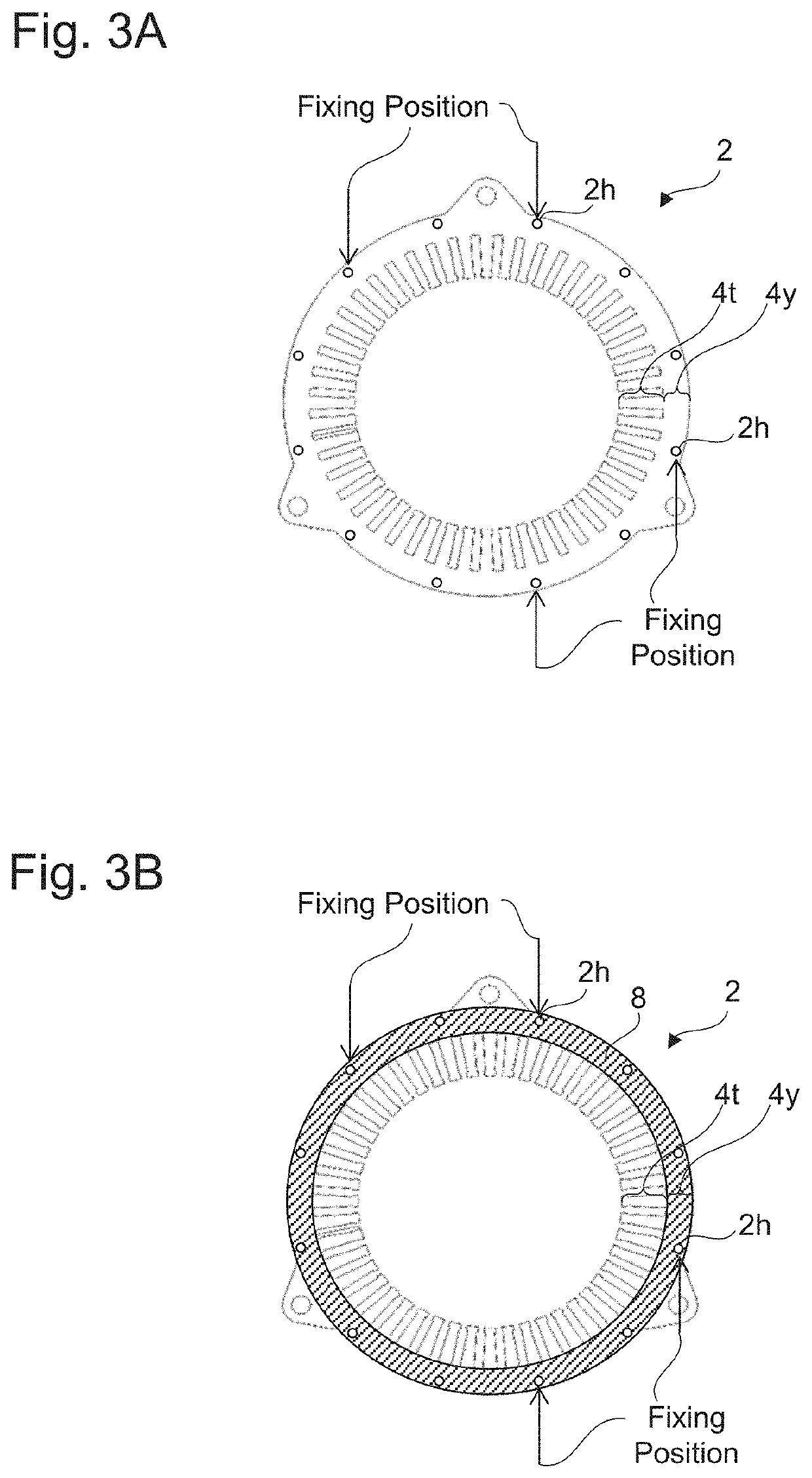
[0024]First, an outline of the motor core according to the first embodiment will be described with the exemplifying drawings. Here, FIG. 1 is a schematic perspective view illustrating the exemplary motor core according to the first embodiment. FIG. 2A is a schematic cross-sectional view illustrating a cross section taken along the line A-A of FIG. 1, FIG. 2B is an enlarged view of a pail X of FIG. 2A, and FIG. 2C is an enlarged view of a part Y of FIG. 2A. FIG. 3A is a schematic plan view illustrating the metal thin plate illustrated in FIGS. 2A to 2C, and FIG. 3B is a schematic plan view illustrating the metal thin plate and the insulation film illustrated in FIGS. 2A to 2C. FIG. 4 is a photograph indicating an exemplary cross section taken along the line B-B of FIG. 1.

[0025]As illustrated in FIG. 1 and FIG. 2A, a motor core 10 according to the first embodiment is a stator core that includes a laminated body 4, a pair of end plates 5, and rivets 6. A plurality of...

second embodiment

II. Second Embodiment

[0052]The following mainly describes differences between the second embodiment and the first embodiment.

[0053]First, an outline of the motor core according to the second embodiment will be described with the exemplifying drawings. Here, FIG. 5A is a schematic cross-sectional view illustrating an exemplary motor core according to the second embodiment, and a schematic cross-sectional view corresponding to FIG. 2A. FIG. 5B is an enlarged view of a part X of FIG. 5A, and. FIG. 5C is an enlarged view of a part Y of FIG. 5A.

[0054]As illustrated in FIG. 5A to FIG. 5C, a motor core 10 according to the second embodiment includes insulation films 8a between metal thin plates (one aspect of the metal plate) 2 in a back yoke portion 4y (peripheral edge portion), and insulation films 8b thinner than those in the back yoke portion 4y between the metal thin plates 2 in a teeth portion 4t (center portion). Accordingly, while, since the pressure in the lamination direction to f...


PUM


Abstract

A motor core that ensures reduction of eddy-current loss and improvement of a space factor at the same time is provided. The motor core according to the present disclosure includes a laminated body where a plurality of metal plates are laminated; a fixing member that fixes the plurality of metal plates to each other at a fixing position in a peripheral edge side of the laminated body; and an insulation film disposed between the metal plates in a peripheral edge portion of the laminated body including the fixing position. In a center portion of the laminated body, no insulation film is disposed between the metal plates, or an insulation film thinner than the insulation film in the peripheral edge portion is disposed between the metal plates.

Description

CROSS REFERENCE TO RELATED APPLICATIONS[0001]The present application claims priority from Japanese patent application JP 2018-213644 filed on Nov. 14, 2018, the content of which is hereby incorporated by reference into this application.BACKGROUNDTechnical Field[0002]The present disclosure relates to a motor core that includes a laminated body in which a plurality of metal plates are laminated.Background Art[0003]Conventionally, for a motor core, a laminated body of metal plates is often used. In the laminated body, a plurality of metal plates, such as electromagnetic steel plates, are insulated from one another by insulators between the plates and laminated to reduce an eddy-current loss.[0004]In the motor core where such a laminated body is used, it is required to reduce the eddy-current loss and, at the same time, it is required to improve a torque performance by increasing a space factor as a proportion of a volume occupied by the metal plates in the laminated body. While the edd...

Claims


Application Information

Patent Timeline
Patent Type & Authority Applications(United States)
IPC IPC(8): H02K15/10H02K3/42
CPCH02K3/42H02K15/10H02K1/16H02K15/024
Inventor MANABE, HIDEKIURATA, SHINYAMAEDA, YOSHITAKA
Owner TOYOTA JIDOSHA KK
Why Eureka
Try Eureka