Stabilizer leg device

Active Publication Date: 2020-05-21
HIAB AB CO CARGOTEC SWEDEN AB
View PDF0 Cites 2 Cited by
  • Summary
  • Abstract
  • Description
  • Claims
  • Application Information

AI Technical Summary

Benefits of technology

The invention relates to a device for controlling the movement of a stabilizer leg in a vehicle. The device includes guiding members that prevent the stabilizer leg from moving when in the working position. When the stabilizer leg needs to be extended or retracted, the guiding members allow the shaft to slide vertically and pivot about the horizontal axis. This allows the stabilizer leg to automatically lock and unlock, without the need for manual adjustment. The first engagement member is a disc with cogs, which engages with the second engagement member, which is a cogged gearwheel or disc. This design is simple and reliable. The technical effects of this invention include improved stability and reliability of the vehicle, as well as simplified and reliable movement of the stabilizer leg.

Problems solved by technology

This locking pin has to be operated manually, which makes the locking and unlocking actions rather complicated to achieve.
Furthermore, such a design has not an optimum reliability, since there is a risk that it is forgotten to carry out the locking action, which may then under extreme conditions result in accidents.

Method used


Image

  • Stabilizer leg device
  • Stabilizer leg device
  • Stabilizer leg device

Examples


Embodiment Construction

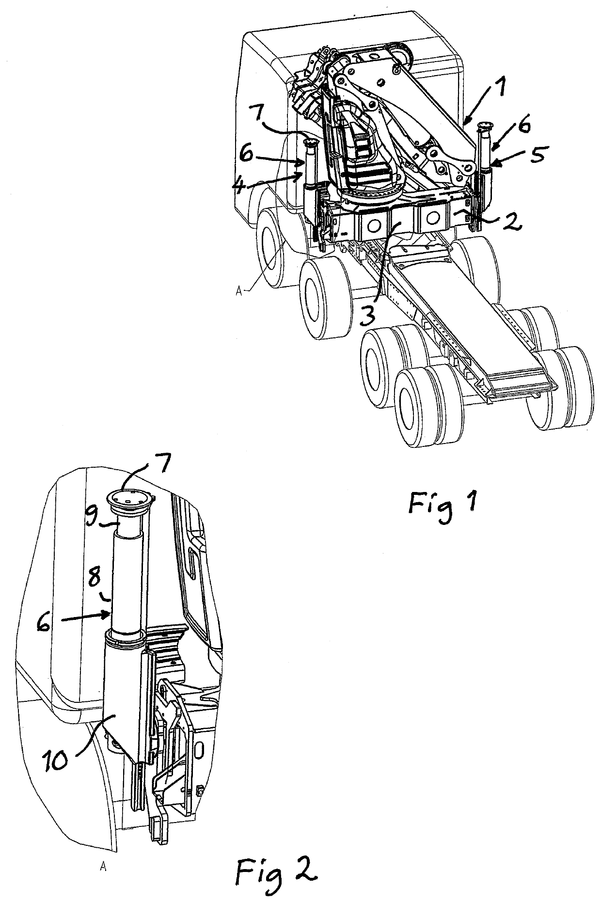
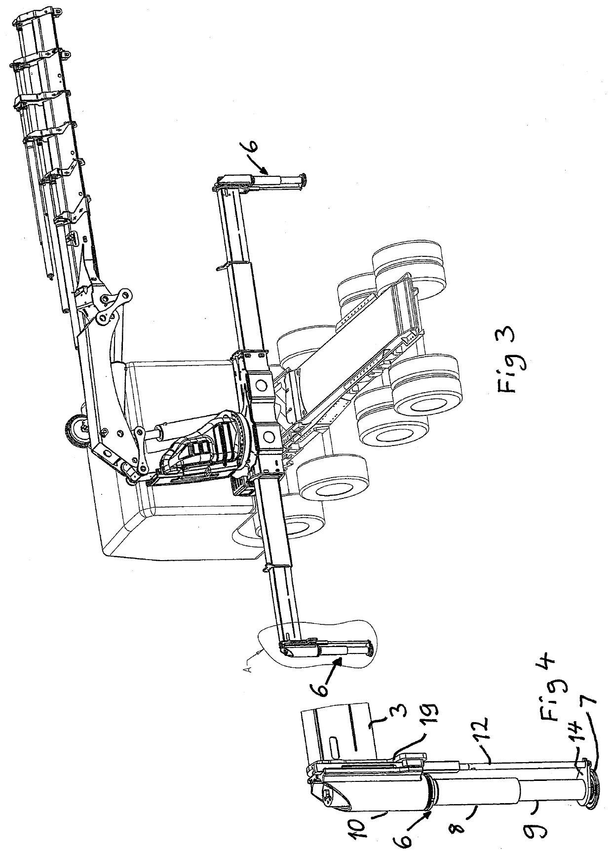
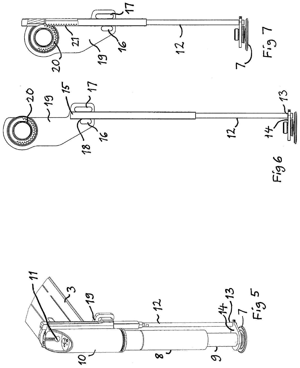
[0029]FIG. 1 shows schematically an object 1 in the form of a crane vehicle to which a support arrangement 2 is fixed by having a frame structure 3 thereof fixed to the framework of the vehicle. The support arrangement is provided with two stabilizer leg devices 4, 5 according the present invention. Each stabilizer leg device has a stabilizer leg 6 to be moved downwards from the crane vehicle while being extended (prolonged) and tilted by 180° from the parking position shown in FIG. 1 so as to stabilize the crane vehicle by bearing through a foot plate 7 secured to a lower end of the stabilizer leg onto the ground on which the vehicle is resting in a working position of the stabilizer leg device, as shown in FIG. 3. FIGS. 2 and 4 are enlarged views showing how a stabilizer leg 6 is arranged on the support arrangement 2 in the parking position and in the working position, respectively, of the stabilizer leg device.

[0030]The design and function of a stabilizer leg device according to ...


PUM


Abstract

A stabilizer leg device with a stabilizer leg to be moved down-wards from an object so as to stabilize the object by bearing through a foot plate (7) on the ground. The device comprises a first engagement member (20) arranged coaxially to a horizontal axis on a part (19) fixed in relation to the object, and a shaft (12) having a first end provided with a second engagement member (21) and an opposite second end arranged to be influenced by movement of a second stabilizer leg member in relation to a first stabilizer leg member to make the shaft slide along the stabilizer leg under extension and retraction of the stabilizer leg so as to cause pivoting of the stabilizer leg by a mutual engagement of said engagement members (20, 21). Members (16, 17) guiding the shaft are designed to automatically unlock and lock, respectively, the stabilizer leg with respect to possibility to pivot about said horizontal axis by passing a predetermined position by the second stabilizer leg member upon retraction and extension of the stabilizer leg.

Description

TECHNICAL FIELD OF THE INVENTION AND BACKGROUND ART[0001]The present invention relates to a stabilizer leg device with a stabilizer leg to be moved downwards from an object, such as a crane vehicle, so as to stabilize this object by bearing through a footplate secured to a lower end of the stabilizer leg onto a support layer on which the object is resting.[0002]Such a stabilizer leg device is normally a part of a support arrangement fixed to such an object, such as a movable crane construction, by a frame structure to which one or more such stabilizer leg devices are secured for stabilizing the crane construction when this has to carry out work.[0003]A stabilizer leg device of this type and with the features listed in the preamble of appended claim 1 is known through EP 0 945 318 A1. The use of first and second engagement members for obtaining a movement of the stabilizer leg from a working position of the stabilizer leg device with the footplate bearing on the ground to a parking p...

Claims


Application Information

Patent Timeline
IPC IPC(8): B66C23/80
CPCB66C2700/0378B66C23/80
Inventor FERRER MORANCHO, JOAQUIN
Owner HIAB AB CO CARGOTEC SWEDEN AB
Why Eureka
Try Eureka