Bandgap voltage reference circuit capable of correcting voltage distortion

Active Publication Date: 2020-05-21
EMEMORY TECH INC
View PDF8 Cites 0 Cited by
  • Summary
  • Abstract
  • Description
  • Claims
  • Application Information

AI Technical Summary

Benefits of technology

The present invention is about a bandgap voltage reference circuit. This circuit includes various components such as current sources, amplifiers, transistors, resistors, and a leakage current compensation element. This circuit can provide a stable reference voltage even at different temperatures and can be used in various electronic devices. The technical effect of this invention is to provide a reliable reference voltage for accurate measurements and control in electronic devices.

Problems solved by technology

However, once the temperature becomes higher than 155V, the bandgap reference voltage will increase dramatically due to the internal leakage current, making the system unstable.

Method used


Image

  • Bandgap voltage reference circuit capable of correcting voltage distortion
  • Bandgap voltage reference circuit capable of correcting voltage distortion
  • Bandgap voltage reference circuit capable of correcting voltage distortion

Examples


Embodiment Construction

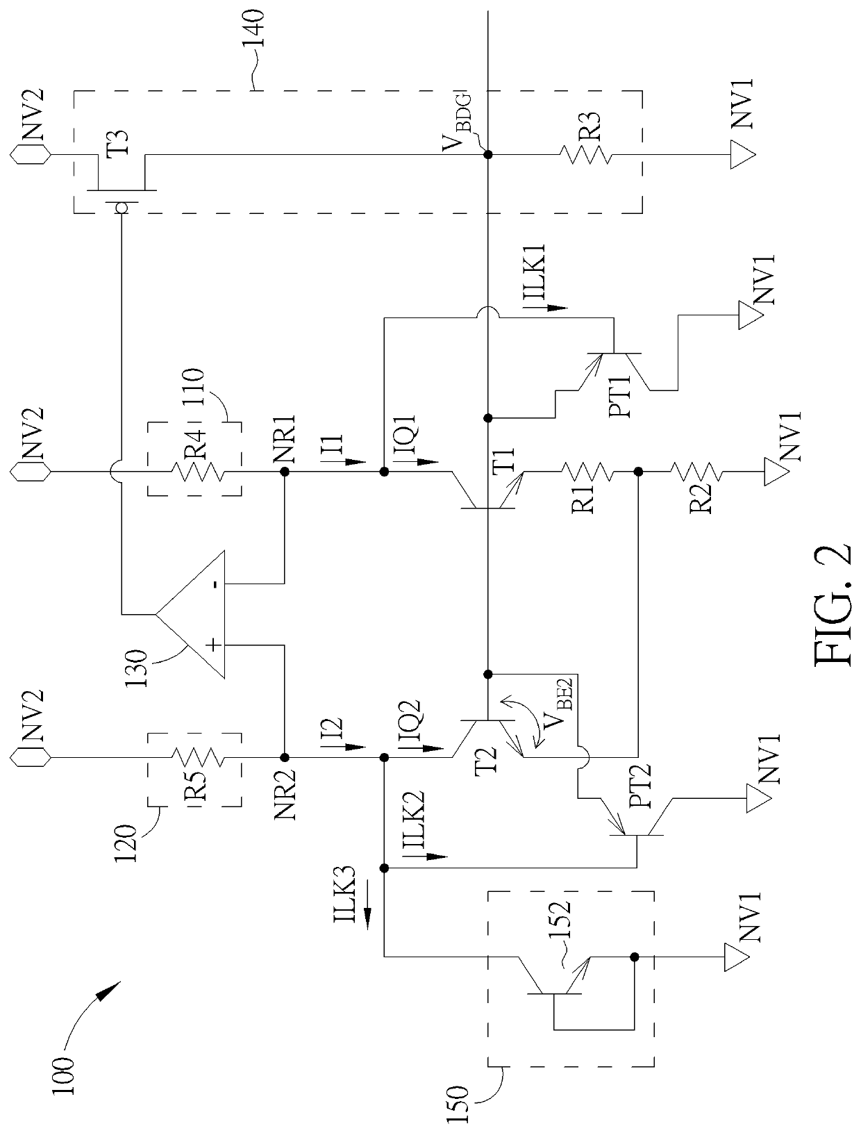
[0015]FIG. 2 shows a bandgap voltage reference circuit 100 according to one embodiment of the present invention. The bandgap voltage reference circuit 100 includes a first current source 110, a second current source 120, an amplifier 130, a voltage buffer 140, a first transistor T1, a first resistor R1, a second resistor R2, a second transistor T2, and a leakage current compensation element 150.

[0016]The first current source 110 can be coupled to a first reference node NR1, and can provide a first current I1. The second current source 120 can be coupled to a second reference node NR2, and can provide a second current I2.

[0017]In FIG. 2, the first current source 110 can include a fourth resistor R4, and the second current source 120 can include a fifth resistor R5. The fourth resistor R4 has a first terminal coupled to a second system voltage terminal NV2 for receiving a second system voltage, and a second terminal coupled to the first reference node NR1. The fifth resistor R5 has a ...


PUM


Abstract

A bandgap voltage reference circuit includes an amplifier, a voltage buffer, a first transistor, a first resistor, a second transistor, a second resistor, and a leakage current. The input terminals of the amplifier are coupled to a first reference node and a second reference node respectively. The voltage buffer is coupled to the output terminal of the amplifier for outputting a bandgap reference voltage. The first transistor is coupled to the first reference node, the second first resistor, and can receive the bandgap reference voltage. The second resistor is coupled to the first resistor and a system voltage terminal. The second transistor is coupled to the second reference node, the first resistor, and can receive the bandgap reference voltage. The leakage current compensation element is coupled to the second transistor and the system voltage terminal. A size of the first transistor is greater than the second transistor.

Description

CROSS REFERENCE TO RELATED APPLICATIONS[0001]This non-provisional application claims priority of US provisional application No. 62 / 768,099, filed on Nov. 16, 2018 and U.S. provisional application No. 62 / 791,870, filed on Jan. 13, 2019 included herein by reference in its entirety.BACKGROUND OF THE INVENTION1. Field of the Invention[0002]The present invention is related to a bandgap voltage reference circuit, and more particularly, to a bandgap voltage reference circuit capable of correcting voltage distortion.2. Description of the Prior Art[0003]A band-gap voltage reference circuit is widely used in integrated circuits for producing a fixed voltage regardless of power supply variations, temperature changes and circuit loading from a device. The fixed voltage can be used as a reference voltage by charge pumps for providing other high voltages required by the system. Therefore, the stability of the band-gap reference voltage can be crucial to the system.[0004]In prior art, although the...

Claims


Application Information

Patent Timeline
IPC IPC(8): G05F3/24G05F3/26G05F3/30H03F3/195
CPCG05F3/24H03F3/195G05F3/267G05F3/30G05F1/56H03F1/32H03F3/3432H03F2200/456
Inventor CHEN, CHIH-CHUN
Owner EMEMORY TECH INC
Why Eureka
Try Eureka