Device and method of video encoding with first and second encoding code

a video and encoding technology, applied in the field of video image encoding devices, can solve the problems of reducing processing speed, reducing processing speed, and reducing so as to reduce the number of processes to be retraced, the effect of increasing the processing speed

Active Publication Date: 2020-05-21
PANASONIC INTELLECTUAL PROPERTY CORP OF AMERICA
View PDF0 Cites 0 Cited by
  • Summary
  • Abstract
  • Description
  • Claims
  • Application Information

AI Technical Summary

Benefits of technology

[0012]One non-limiting and exemplary embodiment provides an encoding method that, in a video image encoding device having a pipeline structure, can suppress an amount of code generated in each block to be equal to or less than a specific maximum value while suppressing a pipeline from being retraced and that can be replaced with a conventional IPCM.
[0017]According to an encoding apparatus of a first aspect of the present disclosure, in a first mode, a residual coefficient generated by a predictive residual encoder is variable-length-coded to generate a coefficient code string, and, in a state in which header information generated by a header code string generator is associated with the coefficient code string, the coefficient code string and the header information are output. On the other hand, in a second mode, without variable-length-coding a residual decoded image generated by a predictive residual decoder, the residual decoded image is directly used as a coefficient code string, and, in a state in which header information generated by a header information code string generator is associated with the coefficient code string, the coefficient code string and the header information are output. The residual decoded image mentioned here is based on the same input image as that of the residual coefficient. In a decoding device, when the residual coefficient is decoded by using prediction information configuring a combination to the coefficient, the same image as the residual decoded image can be obtained. More specifically, pixel information of a reconstructed image finally generated in the decoding device in the first mode is the same as that in the second mode. For this reason, even though the second mode is used, a change in prediction information described in a header code string and re-encoding are not necessary. For this reason, a process in another block in which an encoding process proceeds with reference to prediction information and pixel information of the current block is not influenced at all. Thus, only a coefficient code string can be directly encoded in a PCM mode without retracing the pipeline. Thus, in the encoding device having a pipeline structure, an amount of code generated in each block can be suppressed in an amount equal to or smaller than a specific maximum value without decreasing a processing speed or increasing an amount of processing.
[0018]According to an encoding device of a second aspect of the present disclosure, the same effect as that in the encoding device according to the first aspect can be obtained while variable-length-coding a differential image.
[0019]According to an encoding apparatus of a third aspect of the present disclosure, in a first mode, a residual coefficient generated by a predictive residual encoder is variable-length-coded to generate a coefficient code string, and, in a state in which header information generated by a header code string generator is associated with the coefficient code string, the coefficient code string and the header information are output. On the other hand, in the second mode, a code string obtained without variable-length-coding a differential image output from a subtracter is additionally written subsequently to a code string generated by the header code string generator to generate a final code string. The residual coefficient mentioned here is based on the same input image as that of the residual image. For this reason, even though the current block is switched to a PCM mode, a change of prediction information described in the header code string is unnecessary. However, when a residual coefficient in the decoding device is decoded by using prediction information configuring a combination to the corresponding signal, an image different from the differential image is generated. For this reason, pixel information of a reconstructed image finally obtained in the decoding device when encoding is performed in the first mode is different from that obtained when encoding is performed in the second mode. At this time, an encoding process of another block that refers to pixel information of the current block proceeds. For this reason, even in the other block, the process must be executed again by replacing the pixel information. Thus, the process must retrace an inter / intra prediction process of the current block. However, in comparison with conventional control, since the process does not need to retrace mode determination, the number of processes to be retraced can be reduced. Thus, in the encoding device having a pipeline structure, encoding can be performed while suppressing the pipeline from being retraced. Thus, in the encoding device having a pipeline structure, an amount of code generated in each block can be suppressed in an amount equal to or smaller than a specific maximum value while suppressing a decrease in processing speed or an increase in an amount of processing.

Problems solved by technology

However, it cannot be determined whether the amount of code generated in each block is suppressed in an amount equal to or smaller than the maximum value by an amount of code is examined upon completion of the variable-length-coding.
Controlling to retrace the pipeline requires very complex processing control.
When the number of times of retracing is increased when the IPCM occurs in a target picture many times, a decrease in processing speed is caused, and an encoding process of the target picture cannot be completed in the required time.

Method used


Image

  • Device and method of video encoding with first and second encoding code
  • Device and method of video encoding with first and second encoding code
  • Device and method of video encoding with first and second encoding code

Examples


first embodiment

[0034]A video image encoding device according to a first embodiment will be described below with reference to the drawings.

1. Configuration of Video Image Encoding Device

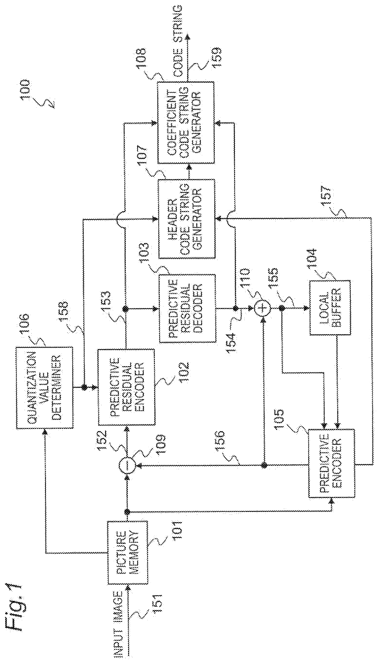
[0035]FIG. 1 is a block diagram showing a configuration of a video image encoding device 100 according to the embodiment. The video image encoding device 100 divides a video image input in units of pictures and performs an encoding process in units of blocks to generate a code string.

[0036]The video image encoding device 100 includes a picture memory 101, a predictive residual encoder 102, a predictive residual decoder 103, a local buffer 104, a predictive encoder 105, a quantization value determiner 106, a header code string generator 107, and a coefficient code string generator 108.

[0037]The picture memory 101 accumulates input image signals 151 input in units of pictures in a display order an re-arranges pictures in an encoding order. When the picture memory 101 accepts a read instruction from a subtracter 109 or...

second embodiment

[0074]A video image encoding device according to the second embodiment will be described below with reference to the accompanying drawings.

1. Configuration of Video Image Encoding Device

[0075]FIG. 7 is a block diagram showing a video image encoding device 100-1 according to the embodiment. The video image encoding device 100-1 divides a video image input in units of pictures into blocks and performs an encoding process in units of blocks to generate a code string.

[0076]The video image encoding device 100-1 includes a coefficient code string generator 108-1 in place of the coefficient code string generator 108 of the video image encoding device 100 in the first embodiment.

[0077]For descriptive convenience, the detailed description of the same configurations as in the first embodiment will be omitted. Furthermore, in FIG. 7, the same numbers as in FIG. 1 denote blocks having the same functions as in FIG. 1.

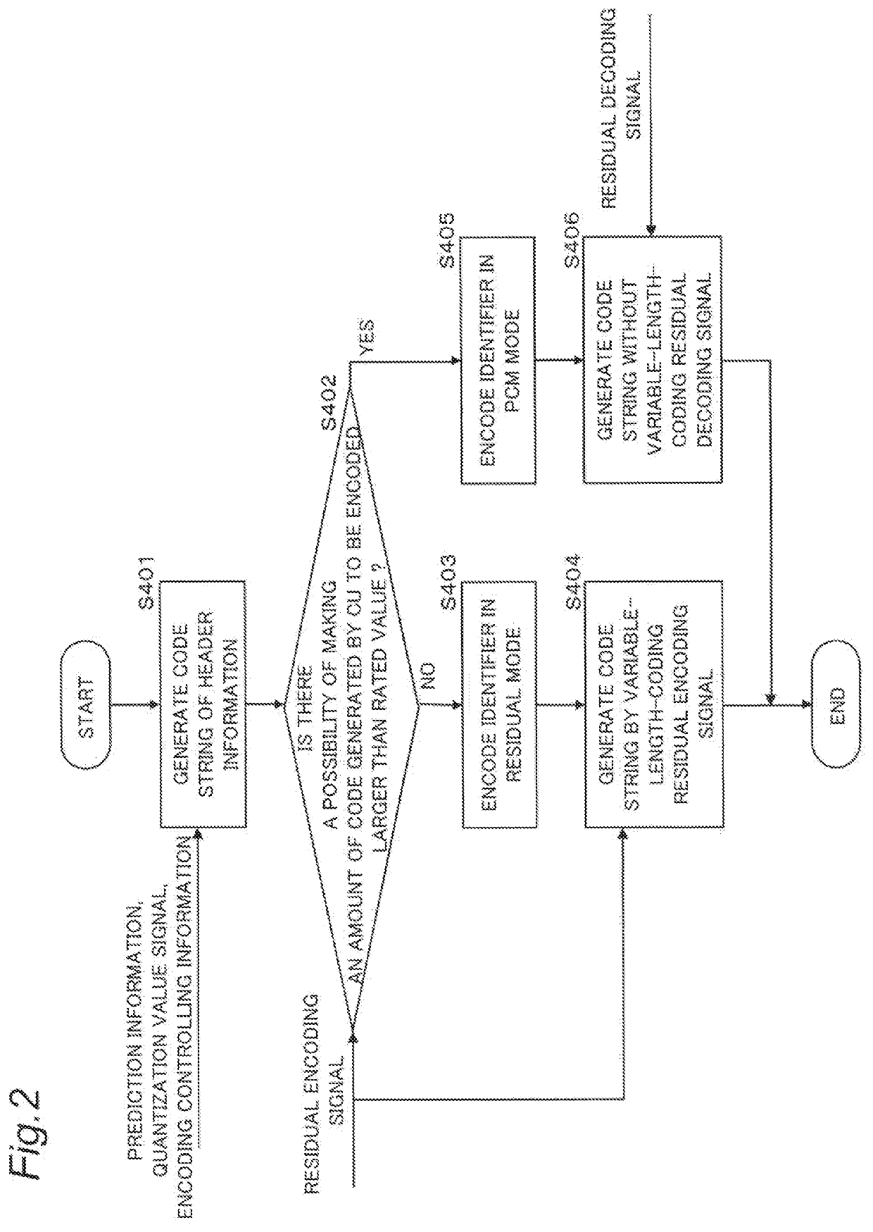
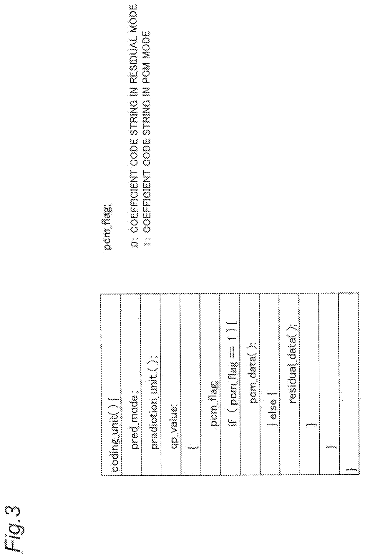
[0078]The coefficient code string generator 108-1 has a first mode in which a c...

third embodiment

[0095]A video image encoding device according to a third embodiment will be described below with reference to the accompanying drawings.

1. Configuration of Video Image Encoding Device

[0096]FIG. 10 is a block diagram showing a video image encoding device 100-2 according to the embodiment. The video image encoding device 100-2 divides a video image input in units of pictures and performs an encoding process in units of blocks to generate a code string.

[0097]The video image encoding device 100-2 includes a coefficient code string generator 108-2 in place of the coefficient code string generator 108 of the video image encoding device 100 in the first embodiment.

[0098]For descriptive convenience, the detailed description of the same configurations as in the first embodiment will be omitted. Furthermore, in FIG. 10, the same numbers as in FIGS. 1 and 7 denote blocks having the same functions as in FIGS. 1 and 7.

[0099]The coefficient code string generator 108-2 executes the operations such...


PUM


Abstract

A video image encoding device, in a first mode, variable-length-encodes a residual coefficient to generate a coefficient code string, outputs the coefficient code string and the header information in a state in which the header information is associated with the coefficient code string, in a second mode, directly uses a differential image as a coefficient code string without variable-length-encoding the differential image, and outputs the coefficient code string and the header information in a state in which the header information is associated with the coefficient code string.

Description

BACKGROUND1. Technical Field[0001]The present disclosure relates to a video image encoding device that encodes a video image such that the video image is divided into blocks.2. Related Art[0002]In recent years, with development of multimedia applications, it has been popularized that information of all kinds of media such as images, sounds, and texts are uniformly handled. Since a digitized image has huge volumes of data, an image information compression technique is indispensable to accumulate and transmit the image. On the other hand, to mutually operate compressed image data, standardization of compression techniques is also important. For example, as standards of measure of image compression techniques, H.261, H.263, and H.264 of ITU-T (telecommunication standardization sector in International Telecommunication Union), MPEG-1, MPEG-3, MPEG-4, and MPEG-4AVC of ISO / IEC (International Organization for Standardization), and the like are given. At present, a standardization action fo...

Claims


Application Information

Patent Timeline
Patent Type & Authority Applications(United States)
IPC IPC(8): H04N19/176H04N19/146H04N19/436H04N19/103
CPCH04N19/103H04N19/50H04N19/436H04N19/176H04N19/146H04N19/42G06T9/004H04N19/124
Inventor OHGOSE, HIDEYUKIABE, KIYOFUMIARAKAWA, HIROSHIJURI, TATSUROKIMURA, KAZUHITO
Owner PANASONIC INTELLECTUAL PROPERTY CORP OF AMERICA
Why Eureka
Try Eureka