Methods and systems for a fuel injector

a fuel injector and fuel technology, applied in mechanical equipment, machines/engines, electric control, etc., can solve the problems of fuel combustion, soot generation, and formation of dense fuel pockets in the combustion chamber, so as to reduce the amount of soot, increase the fuel consumption, and reduce the effect of soo

Active Publication Date: 2019-05-09
FORD GLOBAL TECH LLC
View PDF10 Cites 2 Cited by
  • Summary
  • Abstract
  • Description
  • Claims
  • Application Information

AI Technical Summary

Benefits of technology

[0004]However, the inventors have recognized potential issues with such diesel engines. As one example, diesel fuel may not mix evenly with the air in the combustion chamber, leading to the formation of dense fuel pockets in the combustion chamber. These dense regions of fuel may produce soot as the fuel combusts. As such, conventional diesel engines include particulate filters for decreasing an amount of soot and other particulate matter in their emissions. However, such particulate filters lead to increased cost and increased fuel consumption.
[0005]Modern technologies for combating engine soot output include features for entraining air with the fuel prior to injection. This may include passages located in the injector body, as an insert into the engine head deck surface, or in engine head. Ambient air mixes with the fuel, cooling the injection temperature, prior to delivering the mixture to the compressed air in the cylinder. By entraining cooled air with the fuel prior to injection, a lift-off length is lengthened and start of combustion is retarded. This limits soot production through a range of engine operating conditions, reducing the need for a particulate filter.
[0006]However, the inventors herein have recognized potential issues with such injectors. As one example, the previously described fuel injectors may no longer sufficiently prevent soot production to a desired level in light of increasingly stringent emissions standards. As such, particulate filters may be located in an exhaust passage, thereby increasing a manufacturing cost and packaging restraint of the vehicle.
[0007]In one example, the issues described above may be addressed by a system comprising a combustion chamber comprising a duct comprising at least one flow-through passage configured to receive a fuel injection and combustion chamber gases, the flow-through passage comprising a first diameter upstream of and larger than a second diameter, the second diameter upstream of and larger than a third diameter, and where a first difference between the first and second diameters is greater than a second difference between the second and third diameters. In this way, soot production is limited or prevented when pre-combustion is detected in the passage.
[0008]As one example, the flow-through passage is integrated into one or more of a duct and nozzle tip of the fuel injector. The first diameter corresponding to an inlet of the flow-through passage and the third diameter corresponding to an outlet of the flow through passage. Additionally or alternatively, the first diameter may be the largest diameter of the flow-through passage and the third diameter may be the smallest diameter of the flow-through passage. This may provide the flow-through passage with a substantially trumpet-shape. By doing this, a duration of time a fuel injection resides in the flow-through passage may be decreased relative to flow-through passage having a fixed diameter. In this way, particulate matter output may be mitigated and / or prevented.

Problems solved by technology

Thus, in a diesel engine, the fuel may combust with the air in the combustion chamber due to the high temperature of the air, and may not be ignited via a spark plug as in a gasoline engine.
However, the inventors have recognized potential issues with such diesel engines.
As one example, diesel fuel may not mix evenly with the air in the combustion chamber, leading to the formation of dense fuel pockets in the combustion chamber.
These dense regions of fuel may produce soot as the fuel combusts.
However, such particulate filters lead to increased cost and increased fuel consumption.
However, the inventors herein have recognized potential issues with such injectors.
As one example, the previously described fuel injectors may no longer sufficiently prevent soot production to a desired level in light of increasingly stringent emissions standards.
As such, particulate filters may be located in an exhaust passage, thereby increasing a manufacturing cost and packaging restraint of the vehicle.
In this way, soot production is limited or prevented when pre-combustion is detected in the passage.

Method used


Image

  • Methods and systems for a fuel injector
  • Methods and systems for a fuel injector
  • Methods and systems for a fuel injector

Examples


Embodiment Construction

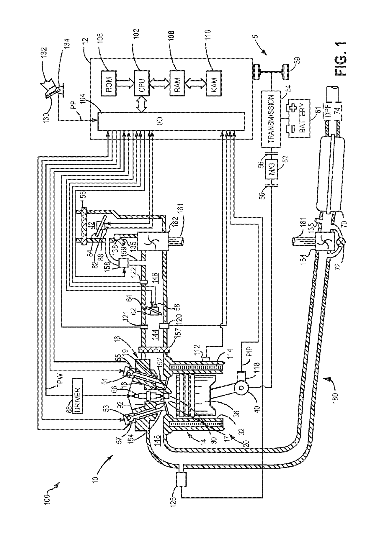
[0017]The following description relates to systems and methods for injecting fuel into an engine cylinder. In particular, the following description relates to systems and methods for injecting diesel fuel. An engine system, such as the engine system shown in FIG. 1, may comprise one or more engine cylinders, each comprising at least one fuel injector. The fuel injectors may be direct injectors that inject fuel directly into the engine cylinders. However, when injected directly into the cylinders, diesel fuel may not mix evenly with the air in the cylinders, leading to pockets in the cylinders of denser and / or less oxygenated fuel where soot may be produced during the combustion cycle.

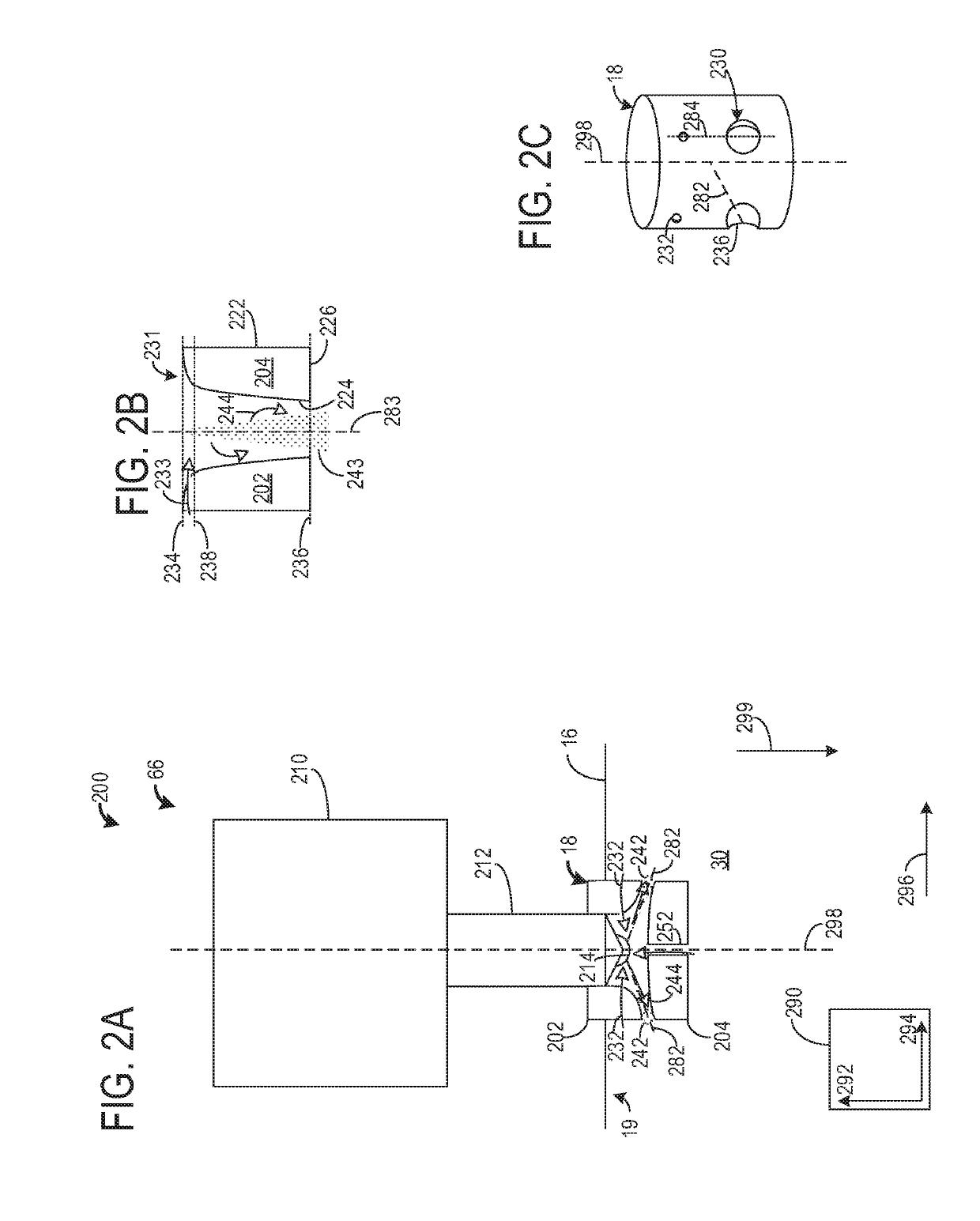
[0018]To reduce the amount of soot produced by an engine, air passages may be included in the engine. Specifically, the air passages may be positioned in a portion of a nozzle of the fuel injector in fluidic communication with and located within the combustion chambers. In this way, gases from a combust...


PUM


Abstract

Methods and systems are provided for a ducted fuel injector. In one example, a method may include adjusting a temperature of combustion chamber gases in a combustion chamber and/or adjusting a fuel rail pressure in response to an amount of light sensed by a photodiode of the duct.

Description

GOVERNMENT RIGHTS[0001]This invention was made with government support under CRADA No. SC16 / 01875.00.00 awarded by the Department of Energy. The government has certain rights in the invention.FIELD[0002]The present description relates generally to methods and systems for a fuel injector comprising air entrainment features.BACKGROUND / SUMMARY[0003]In diesel engines, air is drawn into a combustion chamber during an intake stroke by opening one or more intake valves. Then, during the subsequent compression stroke, the intake valves are closed, and a reciprocating piston of the combustion chamber compresses the gases admitted during the intake stroke, increasing the temperature of the gases in the combustion chamber. Fuel is then injected into the hot, compressed gas mixture in the combustion chamber, resulting in combustion of the fuel. Thus, in a diesel engine, the fuel may combust with the air in the combustion chamber due to the high temperature of the air, and may not be ignited via...

Claims


Application Information

Patent Timeline
Patent Type & Authority Applications(United States)
IPC IPC(8): F02B23/04F02M61/16F02M61/18F02D41/14F02D41/38F02D41/00
CPCF02B23/04F02M61/16F02M61/18F02D41/1439F02D41/3836F02D41/1466F02D41/005F02D2041/389F02M25/03F02D35/02F02D35/022F02D2250/31F02D2250/38F02M57/00F02M2200/24F02M57/005F02B23/0648F02B23/0651F02M25/028F02M26/05F02M26/06Y02T10/12Y02T10/40
Inventor KURTZ, ERIC MATTHEW
Owner FORD GLOBAL TECH LLC
Why Eureka
Try Eureka