Imaging device and parameter adjusting method

Inactive Publication Date: 2020-05-28
QUISDA CORP
View PDF4 Cites 0 Cited by
  • Summary
  • Abstract
  • Description
  • Claims
  • Application Information

AI Technical Summary

Benefits of technology

[0003]An objective of the invention is to provide an imaging device and a parameter adjusting

Problems solved by technology

When the contrast ratio of the two color blocks is larger or smaller than the predetermined threshold, it means that the image q

Method used


Image

  • Imaging device and parameter adjusting method
  • Imaging device and parameter adjusting method
  • Imaging device and parameter adjusting method

Examples


Embodiment Construction

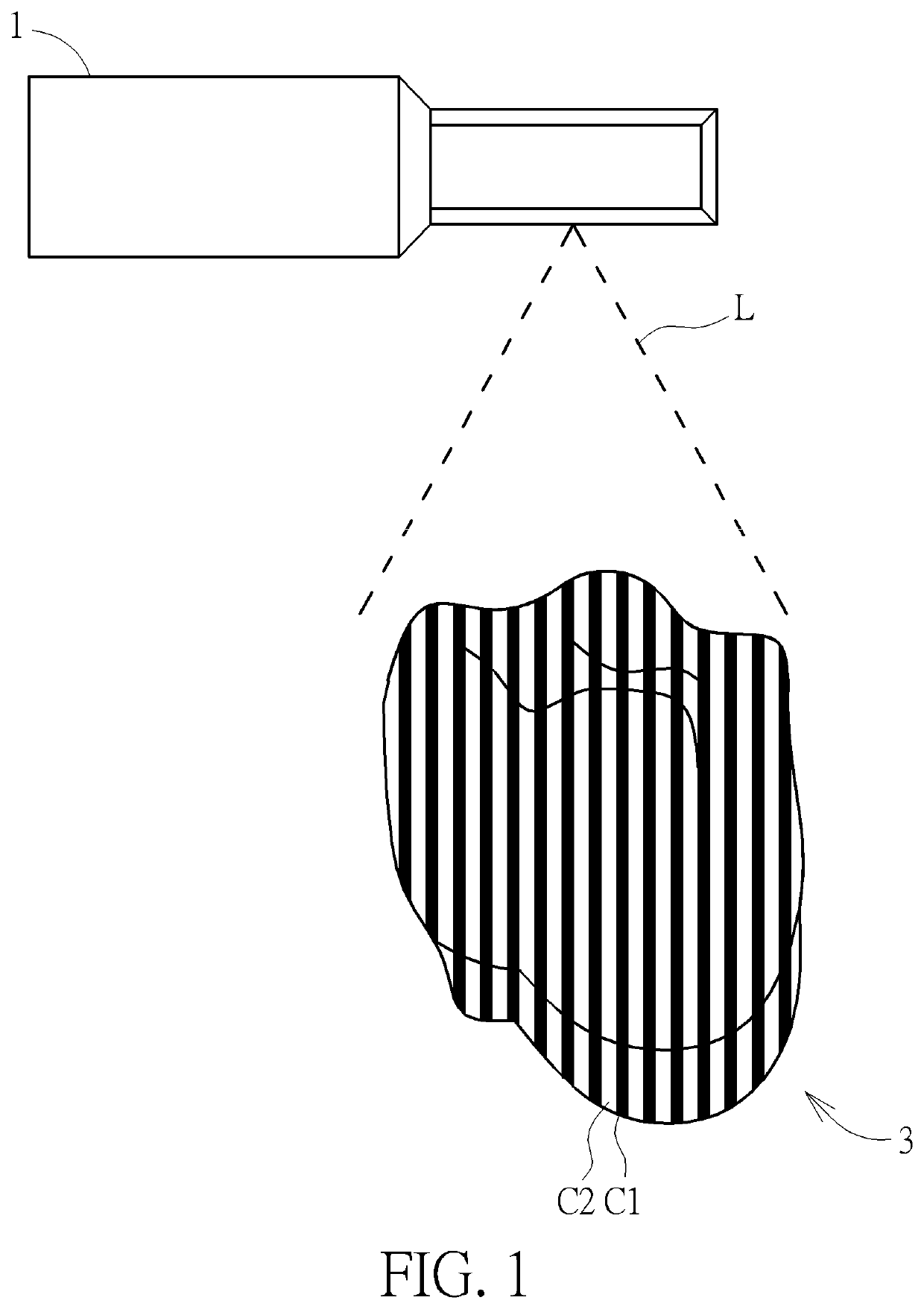
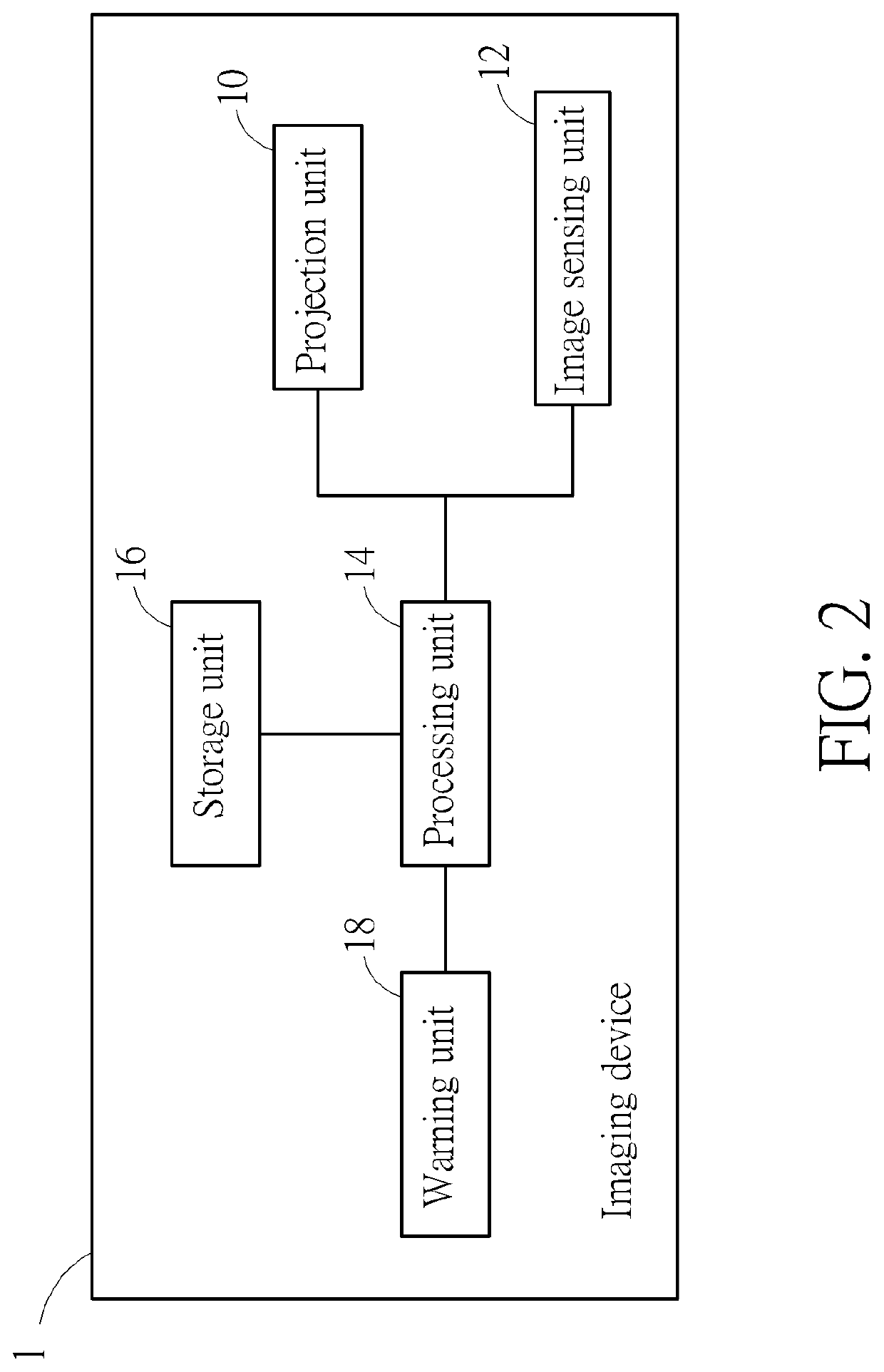
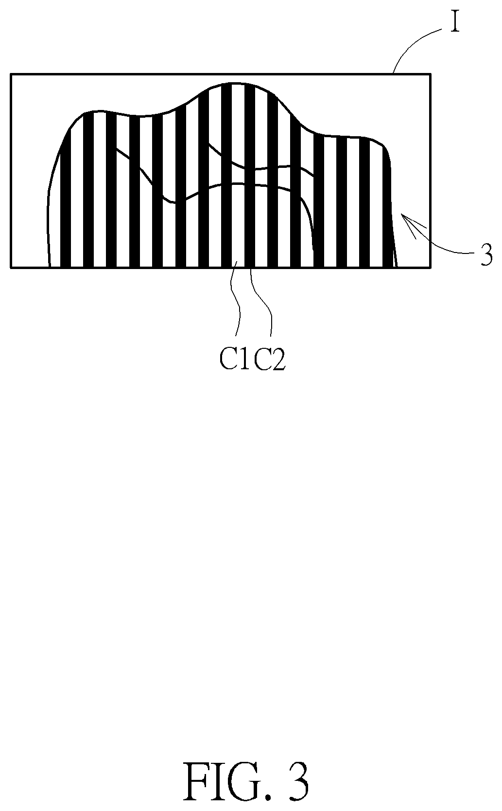
[0013]Referring to FIGS. 1 to 4, FIG. 1 is a schematic diagram illustrating that an imaging device1 is scanning an object 3 according to an embodiment of the invention, FIG. 2 is a functional block diagram illustrating the imaging device 1 shown in FIG. 1, FIG. 3 is a schematic diagram illustrating an image I captured by the image sensing unit 12 shown in FIG. 2, and FIG. 4 is a schematic diagram illustrating a plurality of patterns P1-P3 stored in the storage unit 16 shown in FIG. 2.

[0014]As shown in FIG. 1, the imaging device 1 of the invention is used to scan an object 3, so as to establish a 3D model of the object 3. In this embodiment, the imaging device 1 may be, but not limited to, an intraoral scanner and the object 3 may be, but not limited to, a tooth. In another embodiment, the imaging device 1 may be a projection screen and the object 3 may be a projection plane. In another embodiment, the imaging device 1 may be a 3D model establishing device and the object 3 may be any...


PUM


Abstract

An imaging device includes a projection unit, an image sensing unit and a processing unit. The projection unit is controlled by a projection parameter to project a light onto an object, wherein the light forms two color blocks on the object. The image sensing unit is controlled by an image capturing parameter to capture an image of the object, wherein the image includes the two color blocks. The processing unit analyzes the image to calculate a contrast ratio of the two color blocks. The processing unit compares the contrast ratio with a predetermined threshold. When the contrast ratio is larger or smaller than the predetermined threshold, the processing unit selectively adjusts at least one of the projection parameter and the image capturing parameter. The processing unit controls the projection unit to project the light onto the object and controls the image sensing unit to capture the image of the object.

Description

BACKGROUND OF THE INVENTION1. Field of the Invention[0001]The invention relates to an imaging device and a parameter adjusting method and, more particularly, to an imaging device and a parameter adjusting method capable of improving image quality effectively.2. Description of the Prior Art[0002]An intraoral scanner uses laser to scan tooth rapidly and then transmits the scanned image to a computer, so as to establish a tooth model. In general, the light intensity projected by the intraoral scanner is constant during the process of scanning tooth. However, different tissues or substances in an oral cavity may absorb or reflect different amounts of light and different materials filled in the tooth may also have different characteristics. Accordingly, during the process of scanning tooth, the projected brightness at some positions may be high and the projected brightness at some other positions may be low, such that the image quality will be affected. Furthermore, the length of the exp...

Claims


Application Information

Patent Timeline
IPC IPC(8): H04N5/235G06T7/521
CPCG06T2207/30036H04N5/2351G06T7/521H04N5/238H04N5/243H04N9/735H04N5/2353G06T2207/10028H04N9/3179H04N23/56H04N23/71H04N23/73H04N23/74H04N23/75H04N23/76H04N23/88
Inventor HUANG, MIN-HSIUNG
Owner QUISDA CORP
Why Eureka
Try Eureka