Sound source detecting method and detecting device

a detection method and sound source technology, applied in the direction of direction finders, instruments, speech analysis, etc., can solve the problem of low estimation accuracy of the position of the sound sour

Active Publication Date: 2020-06-04
ONFUTURE LTD
View PDF27 Cites 8 Cited by
  • Summary
  • Abstract
  • Description
  • Claims
  • Application Information

AI Technical Summary

Benefits of technology

[0032]With the detection method for a sound source according to the invention A1 and the detection device therefor according to the invention B1, it is possible to detect the position of a sound source through use of the measurement results of the sound intensities more accurately than a detection method and a detection device that do not include the first extraction step (means) and the first estimation step (means).
[0033]Further, with the det

Problems solved by technology

There is no other way but to state that such results h

Method used


Image

  • Sound source detecting method and detecting device
  • Sound source detecting method and detecting device
  • Sound source detecting method and detecting device

Examples


first embodiment

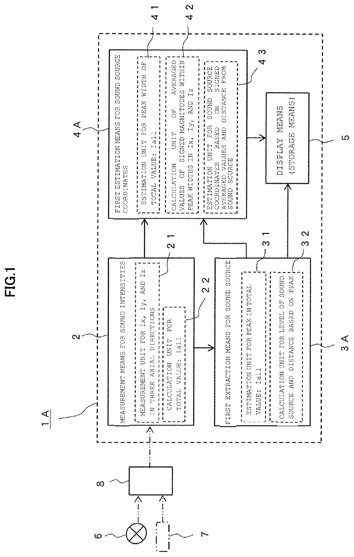
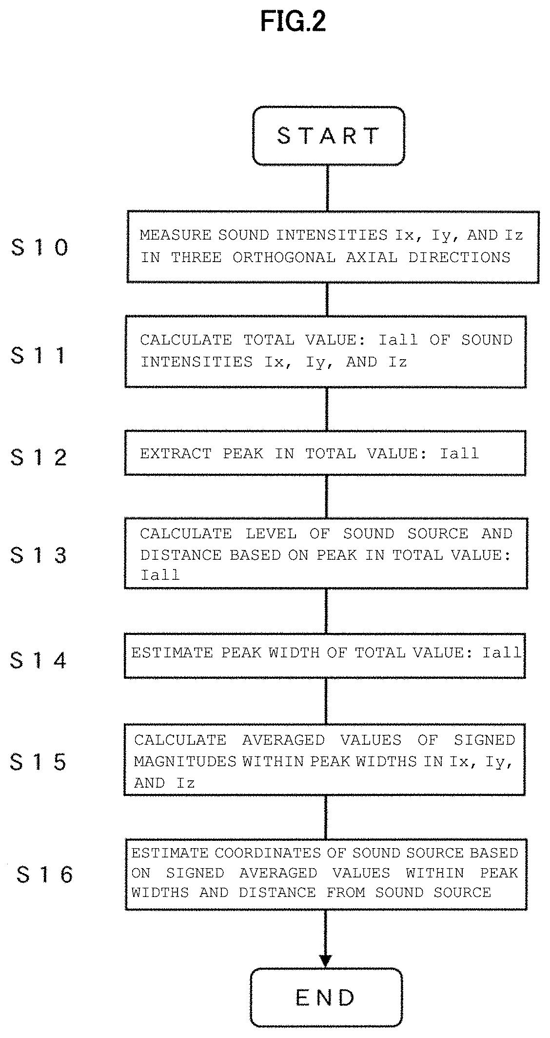
[0057]In FIG. 1 and FIG. 2, there are illustrated outlines of a detection method for a sound source and a detection device therefor according to a first embodiment. FIG. 1 is an illustration of the outline of the detection device for the sound source, and FIG. 2 is an illustration of the outline (steps) of the detection method for a sound source.

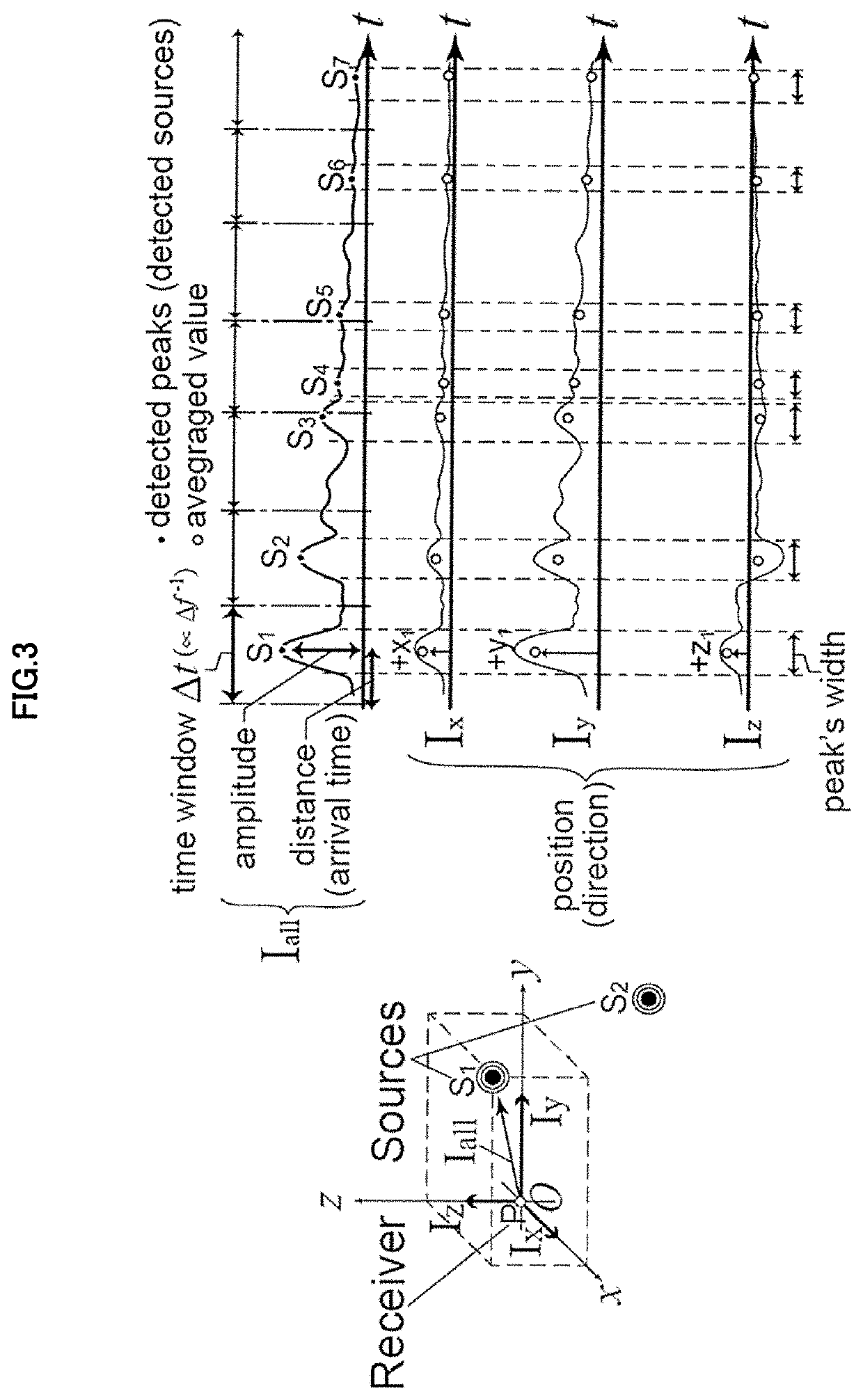
[0058]A detection device 1A for a sound source according to the first embodiment is a device capable of implementing the detection method fora sound source according to the first embodiment . Compared to a method 4 of detecting sound source information from sound intensities through use of “peak detection”, which is described above, this detection method has a feature that the method 4 has been improved so as to be able to estimate a sound source position after extracting a sound source by performing processing with averaged values within a predetermined peak width instead of the magnitudes of peaks in the waveforms of the sound intensities....

second embodiment

[0106]In FIG. 6 and FIG. 7, there are illustrated outlines of a detection method for a sound source and a detection device therefor according to a second embodiment. FIG. 6 is an illustration of the outline of the detection device for the sound source, and FIG. 7 is an illustration of the outline (steps) of the detection method for a sound source.

[0107]A detection device 1B for a sound source according to the second embodiment is a device capable of implementing the detection method for a sound source according to the second embodiment. Unlike the method 4 of detecting the sound source information from the sound intensities through use of the “peak detection” and the detection method according to the first embodiment, this detection method has a feature that the estimation of the sound source position is suitably executed after extracting the sound source with attention being given to a spatial travel speed of a sound intensity or a sound particle velocity without using the peak det...


PUM


Abstract

Provided are a detection method for a sound source and a detection device therefor, which are capable of accurately detecting the position of a sound source through use of measurement results of sound intensities. In the detection method, Iall=√(Ix2+Iy2+Iz2), which is a total value of the sound intensities Ix, Iy, and Iz in three axial directions (x-, y-, and z-axis directions) orthogonal to each other at a sound receiving point (P) in a sound field, is calculated, and then the position of the sound source is estimated after extracting the sound source by performing processing with averaged values within a predetermined peak width instead of the magnitude of a peak in a sound intensity waveform of the total value, or the position of the sound source is estimated after extracting the sound source with attention being given to a spatial travel speed of a sound intensity or a sound particle velocity of the total value.

Description

TECHNICAL FIELD[0001]The present invention relates to a detection method for a sound source and a detection device therefor, and more particularly, to a detection method for a sound source and a detection device therefor that use measurement results of sound intensities.BACKGROUND ART[0002]As methods of measuring the behavior of sound in a three-dimensional space, there are known methods exemplified as follows.[0003]One of the exemplified methods is a method 1 (see FIG. 15 of Non Patent Literature 1), in which sound intensities in three orthogonal axial directions (x-, y-, and z-axis directions) are measured, and measurement results thereof are used to analyze, for example, reflected sounds (hereinafter referred to as “reflections”) in a concert hall so as to identify what kind of sound has arrived from which direction at which timing.[0004]The exemplified methods also include a method 2 (see FIG. 16 of Non Patent Literature 2) and a method 3 (see FIG. 17 of Non Patent Literature 3)...

Claims


Application Information

Patent Timeline
IPC IPC(8): G10L25/51G10L25/03G01S5/18
CPCG10L25/51G10L25/03G01S5/18G01S3/8034G01S5/28G01S11/14G01H3/00
Inventor NAKAHARA, MASATAKA
Owner ONFUTURE LTD
Why Eureka
Try Eureka