Lathe

a technology of lathes and tools, applied in the field of lathes, can solve the problems and achieve the effect of increasing the size of the machine and increasing the cost of the machin

Inactive Publication Date: 2020-06-11
STAR MICRONICS
View PDF0 Cites 3 Cited by
  • Summary
  • Abstract
  • Description
  • Claims
  • Application Information

AI Technical Summary

Benefits of technology

[0004]The entire turret having the decentered turret head with respect to the B-axis occupies a larger area during rotation on the B-axis, which increases the size of the machine. A servo motor for rotating the turret head on the turret axis is needed while another servo motor for rotating the entire turret on the B-axis is also needed, which increases the cost of the machine. Such problem resides in various kinds of lathes.

Problems solved by technology

The entire turret having the decentered turret head with respect to the B-axis occupies a larger area during rotation on the B-axis, which increases the size of the machine.
A servo motor for rotating the turret head on the turret axis is needed while another servo motor for rotating the entire turret on the B-axis is also needed, which increases the cost of the machine.
Such problem resides in various kinds of lathes.

Method used


Image

  • Lathe
  • Lathe
  • Lathe

Examples


embodiment 1

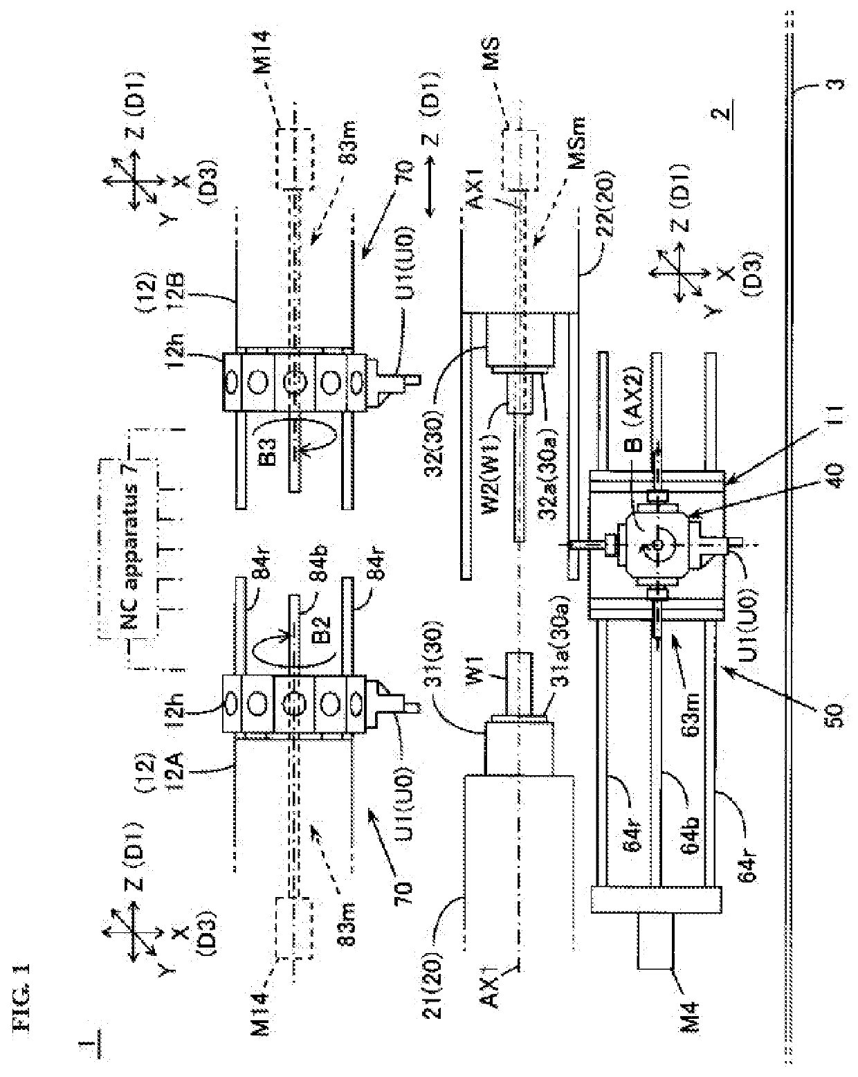
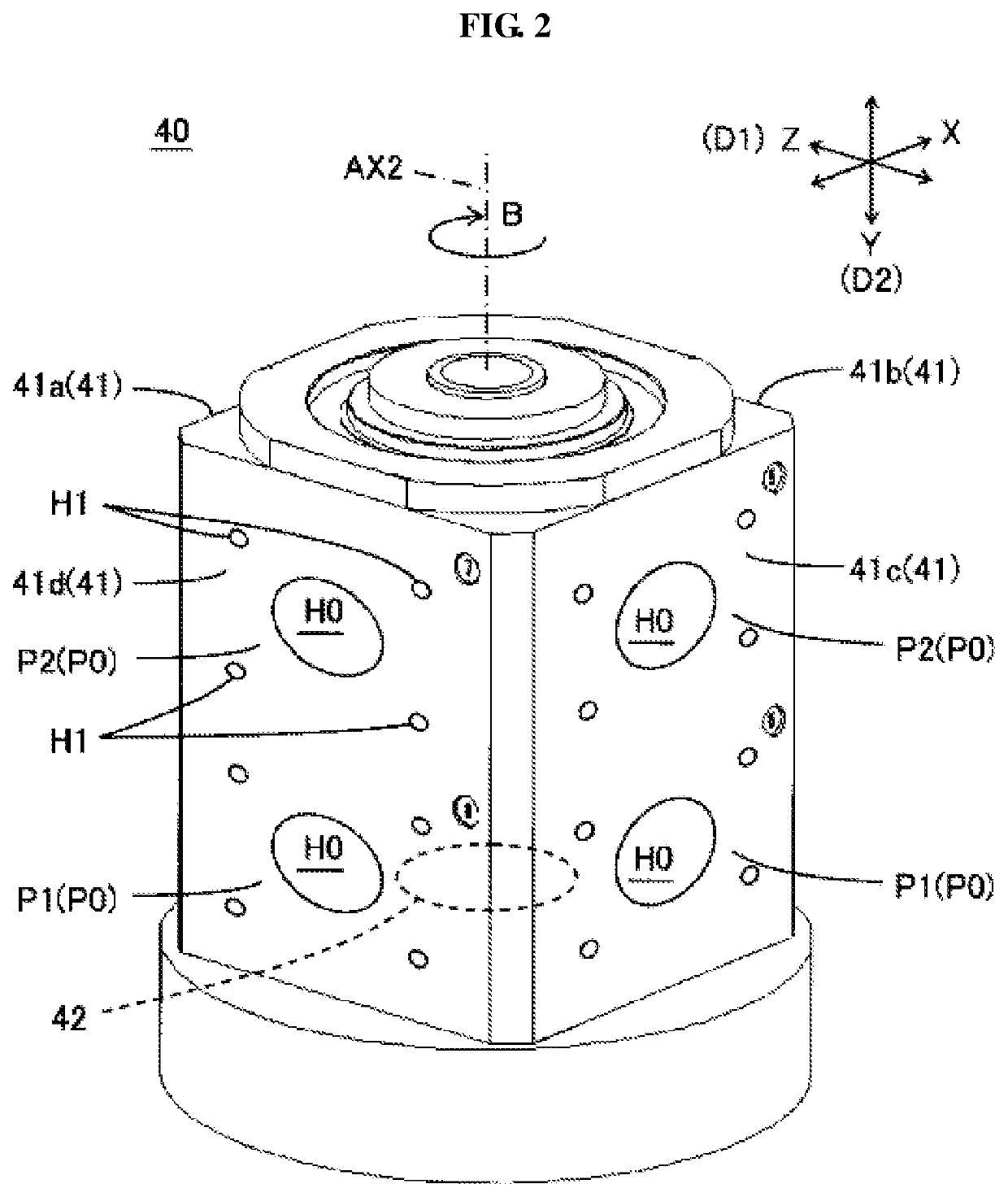
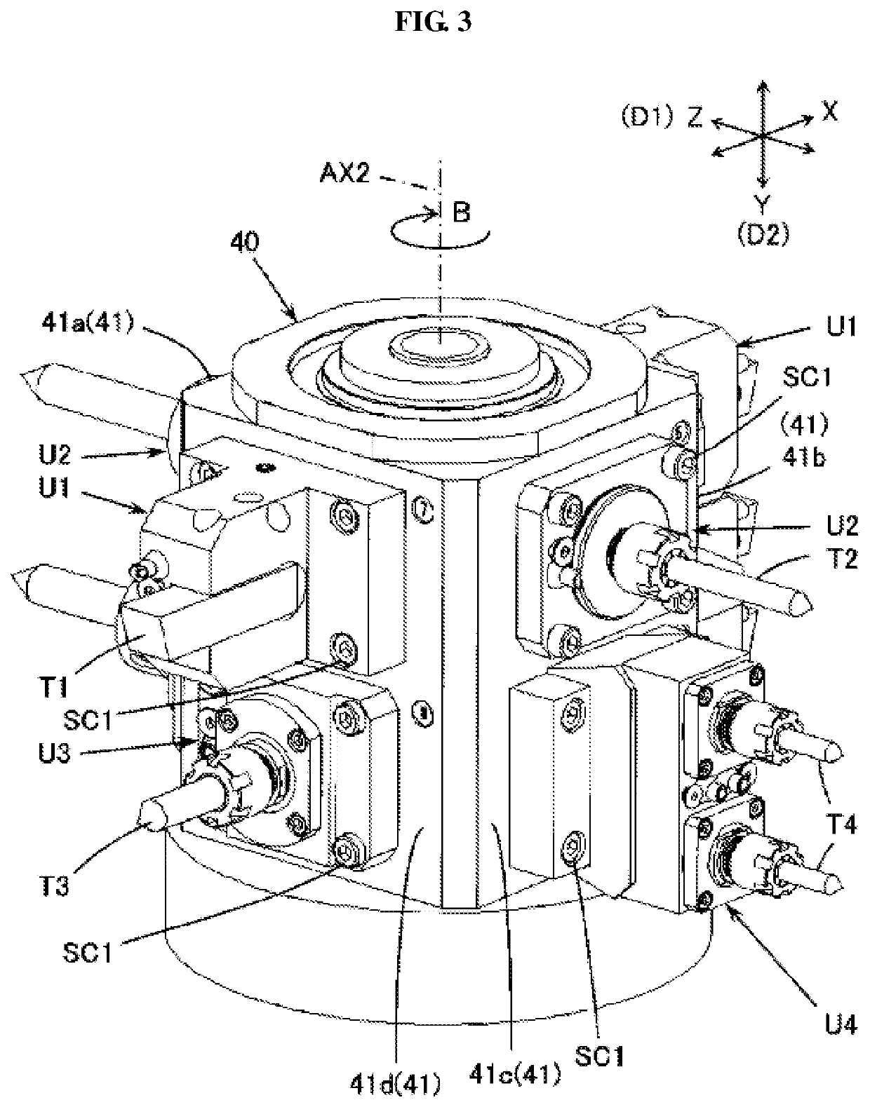
[0018]A lathe 1 of an embodiment of the invention comprises a spindle 30, a turret head 40, and a switching driving unit 51. The spindle 30 rotates a workpiece W1 on a spindle axis AX1. The turret head 40 may have a plurality of turret surfaces 41 to which a tool unit U0 are radially attached around an indexing axis AX2. The tool unit U0 may be attached on a plurality of attaching positions P0 provided on at least part of the plurality of turret surfaces 41. The plurality of attaching positions P0 are arranged in an indexing axis direction D2 along the indexing axis AX2. The turret head 40 is driven by the switching driving unit 51 to be rotated on the indexing axis AX2 and also to be moved in the indexing axis direction D2. The tool units U0 for use are thereby switched.

[0019]The tool units U0 for use are switchable only by rotating the turret head 40 on the indexing axis AX2 and by moving the same in the indexing axis direction D2. The invention eliminates the need of rotating the...

embodiment 2

[0020]The indexing axis direction D2 may be a different direction from a spindle axis direction D1 of the spindle axis AX1. The lathe 1 may further comprise a Z-axis driving unit 52 which moves the turret head 40 in the spindle axis direction D1. Moving the turret head 40 in the spindle axis direction D1 enables the machine to execute various operations on the workpiece W1 without the need of the spindle 30 moving in the spindle axis direction D1. The embodiment provides a technology desired for a lathe of stationary headstock type.

embodiment 3

[0021]The lathe 1 may further comprise an opposite tool post 12 arranged on the opposite side of the turret head 40 across the workpiece W1 in a tool post opposite direction D3. The tool post opposite direction D3 may be a different direction from the indexing axis direction D2 and the spindle axis direction D1. The lathe 1 may further comprise a first opposite driving unit 53 which moves the turret head 40 in the tool post opposite direction D3. The lathe 1 may further comprise a second opposite driving unit 71 which moves the opposite tool post 12 in the tool post opposite direction D3. The embodiment enables the lathe to perform balance-cut and various simultaneous operations on the workpiece W1 by using the tool unit U0 attached to the turret head 40 and the tool unit U0 attached to the opposite tool post 12. The embodiment provides an improvement in productivity.


PUM

PropertyMeasurementUnit
angleaaaaaaaaaa
angleaaaaaaaaaa
sizeaaaaaaaaaa

Abstract

A technology capable of downsizing the lathe is provided. The lathe comprises a spindle which rotates a workpiece on a spindle axis, a turret head, and a tool unit switching driving unit. The turret head has a plurality of turret surfaces to which a tool unit is radially attached around an indexing axis. To at least part of the turret surfaces, the tool unit is attached in a plurality of attaching positions provided in an indexing axis direction along the indexing axis. The tool unit switching driving unit rotates the turret head on the indexing axis and moves the turret head in the indexing axis direction to switch the tool units for use to machine the workpiece.

Description

CROSS-REFERENCE TO RELATED APPLICATION[0001]The present application is a continuation of PCT Application No. PCT / JP2018 / 032199, filed on Aug. 30, 2018, which claims priority of Japanese Patent Application No. 2017-204905 filed on Oct. 24, 2017. The contents of this application are incorporated herein by reference in their entirety.BACKGROUND(a) Field[0002]The present invention relates to a lathe having a spindle and a turret.(b) Description of the Related Art[0003]An NC (numerical control) lathe provided with a front spindle and a back spindle which each rotates a workpiece on a spindle axis and further with a turret is well known. In an NC lathe disclosed in Japanese Unexamined Patent Application Publication (Translation of PCT Application) No. 2014-518777, a tool turret head having a dozen of turret surfaces is mounted on a second tool post in a rotatable manner around a turret axis. The second tool post is rotated on a B-axis perpendicular to the turret axis. The tool turret head...

Claims


Application Information

Patent Timeline
Patent Type & Authority Applications(United States)
IPC IPC(8): B23B3/16
CPCB23B3/161B23B3/16B23B7/04B23B29/24B23Q1/625B23Q1/4871B23Q2039/004B23Q39/025B23B29/246B23B29/32
Inventor KAWASUMI, MASAHIRO
Owner STAR MICRONICS
Why Eureka
Try Eureka