Vane gas compressor having two discharge passages with the same length

a gas compressor and discharge passage technology, applied in the direction of machines/engines, rotary/oscillating piston pump components, liquid fuel engines, etc., can solve the problem that the pulsating motion of the expelled gas is not readily transmitted to the outside, and achieve the effect of increasing the size of the whole machine, reducing noise, and increasing fabrication costs

Inactive Publication Date: 2005-03-29
CALSONIC COMPRESSOR INC
View PDF7 Cites 9 Cited by
  • Summary
  • Abstract
  • Description
  • Claims
  • Application Information

AI Technical Summary

Benefits of technology

Accordingly, it is an object of the present invention to provide a sliding-vane rotary gas compressor in which pulsations of discharging refrigerant gas are suppressed without increasing the size of the whole machine and without increasing the fabrication cost, thereby reducing noise due to the pulsations.

Problems solved by technology

As a consequence, the pulsating motions of the expelled gas are not readily transmitted to the outside.

Method used


Image

  • Vane gas compressor having two discharge passages with the same length
  • Vane gas compressor having two discharge passages with the same length
  • Vane gas compressor having two discharge passages with the same length

Examples


Embodiment Construction

The preferred embodiments of the present invention are hereinafter described in detail by referring to FIGS. 1-7.

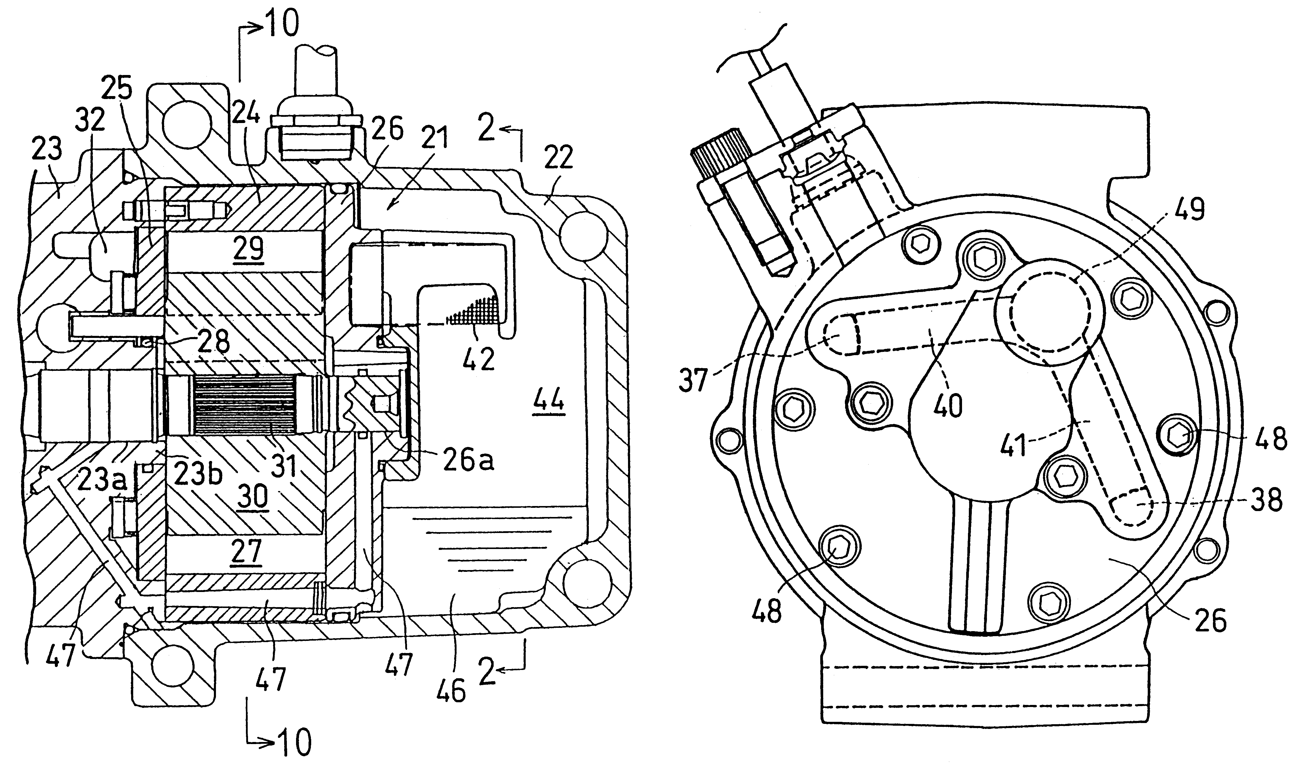
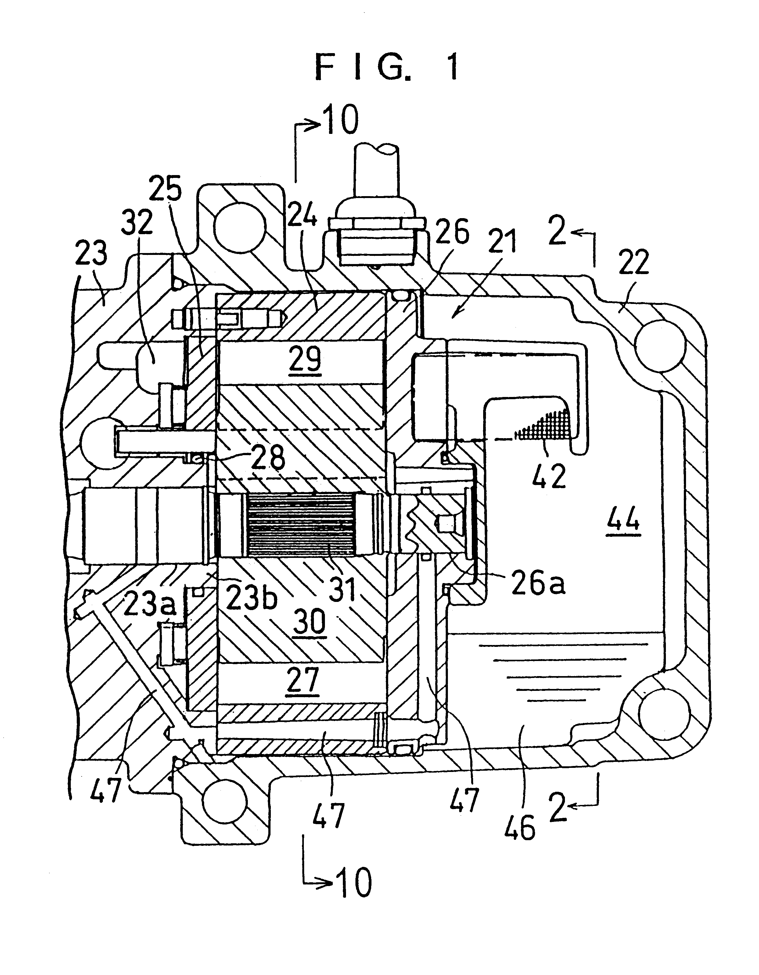
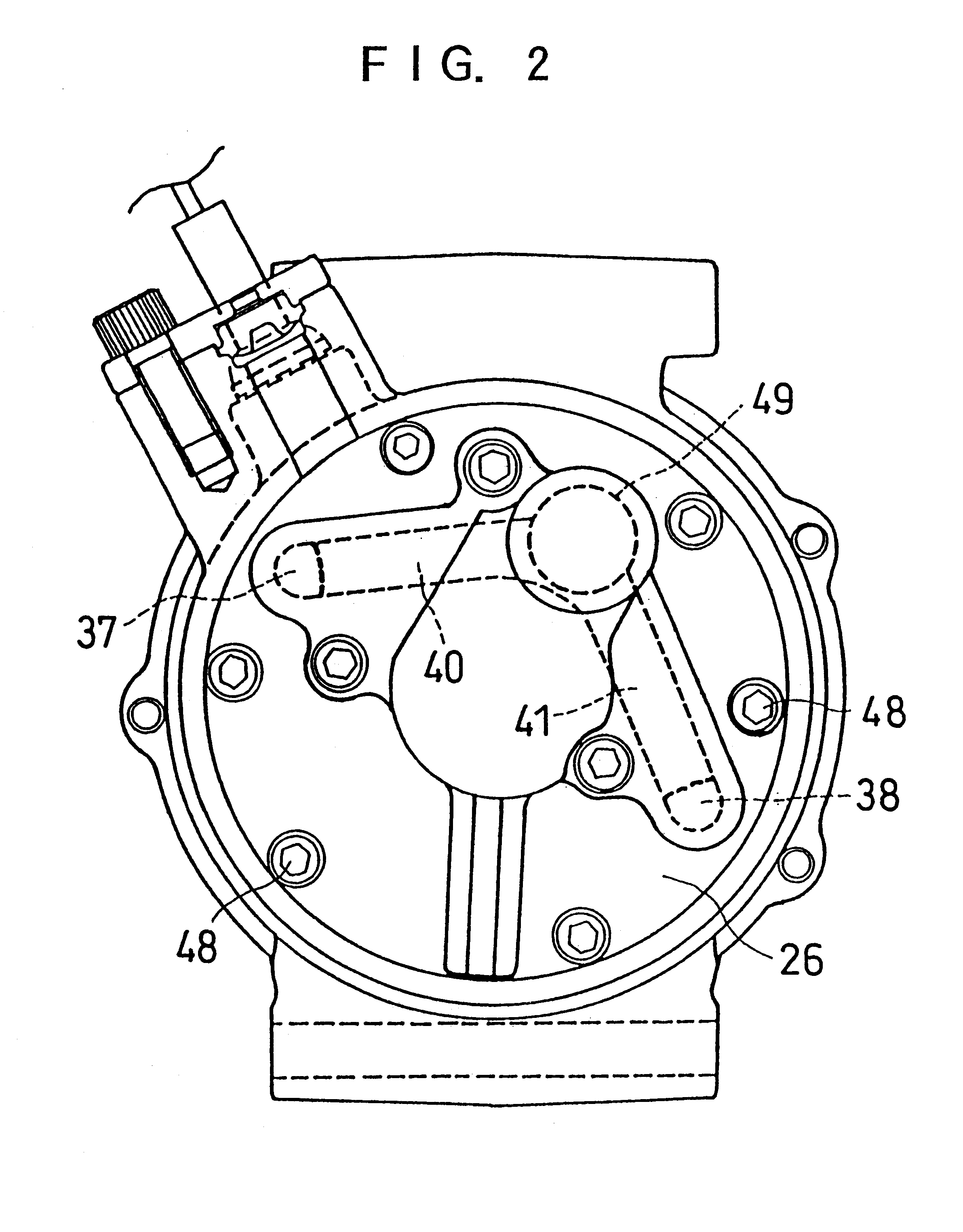
FIG. 1 is a partially cutaway cross section of a gas compressor according to the present invention. FIG. 2 is a view taken on line 2—2 of FIG. 1. FIG. 10 is a view taken on line 10—10 of FIG. 1. As shown in FIG. 1, the gas compressor comprises a gas compression portion 21, a casing 22 surrounding the gas compression portion 21, and a front head 23. The casing 22 has an opening at its one side. The front head 23 is mounted so as to close off the opening in the front head 23.

The gas compression portion 21 comprises a cylindrical block 24, a control plate 25 rotatably mounted to the left end surface of the cylindrical block 24 as described later, and a rear-side block 26 firmly secured to the right end surface of the cylindrical block 24. The axial cross section of the inner surface of the cylindrical block 24 assumes an elliptical form. An elliptical cylinder chamber 27 is ...


PUM


Abstract

A gas compressor has a cylinder chamber provided with discharge holes. Openings are in communication with the discharge holes, respectively. Discharge passages having the same length are connected with the openings, respectively. The ends of the discharge passages are connected with a common passage. During operation of the cylinder chamber, discharge valves cause the expelled gas to produce pulsations on the upstream side of the two openings. The pulsations are shifted in phase by a half wavelength. Noise due to the pulsations is reduced, because the pulsations of the expelled gas cancel out each other when the gas flows through the common passage.

Description

BACKGROUND OF THE INVENTIONThe present invention relates to a gas compressor used in a refrigerator or air-conditioner and, more particularly, to a sliding-vane rotary compressor.FIG. 8 schematically shows the prior art sliding-vane rotary gas compressor in cross section. FIG. 9 is a view taken on line 9—9 of FIG. 8. This gas compressor has a rotor 2 rigidly secured to a rotor shaft 1. When the rotor 2 is driven by a motor (not shown), five vanes 3 slidably held in five slots (not shown), respectively, radially formed in the rotor 2 are rotated in contact with the inner wall of the cylinder chamber 4, thus compressing refrigerant gas.An intake chamber 6 is formed inside a front head 5. An intake port 7 for drawing in the refrigerant gas to be compressed from an evaporator (not shown) is formed over the intake chamber 6. Two intake holes 8 and 9 are formed in the front head 5 symmetrically about a point to place the intake chamber 6 and the cylinder chamber 4 in communication with ea...

Claims


Application Information

Patent Timeline
Patent Type & Authority Patents(United States)
IPC IPC(8): F04C29/06F04C29/12
CPCF04C29/061F04C29/068F04C29/12Y10S418/01F04C2250/102
Inventor SHIMADA, KOICHIYODA, SEIICHIRO
Owner CALSONIC COMPRESSOR INC
Why Eureka
Try Eureka