
Robot system and coupling method

a robot system and coupling technology, applied in the field of robot systems and coupling methods, can solve problems such as difficult changes in work

Active Publication Date: 2020-06-11
SEIKO EPSON CORP
View PDF0 Cites 4 Cited by
  • Summary
  • Abstract
  • Description
  • Claims
  • Application Information

AI Technical Summary

Benefits of technology

The patent aims to solve issues by providing different embodiments. It proposes various solutions to overcome obstacles and achieve desired outcomes.

Problems solved by technology

Accordingly, for example, for changing the control program, the changing work is not easy depending on the contents to change and the degree of proficiency of a programmer.

Method used


Image

  • Robot system and coupling method
  • Robot system and coupling method
  • Robot system and coupling method

Examples


first embodiment

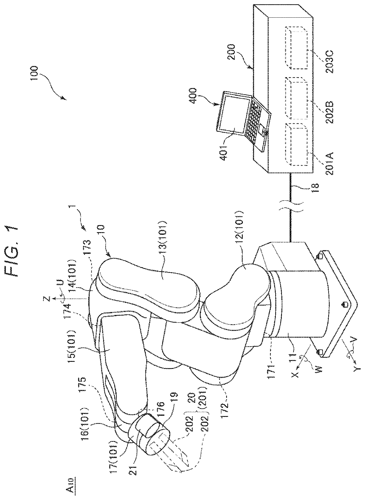
[0045]As shown in FIG. 1, a robot system 100 includes a robot 1 and a robot control apparatus (hereinafter, simply referred to as “control apparatus”) 200 that controls the robot 1, and executes the coupling method according to the present disclosure.

[0046]The robot 1 is a single-arm six-axis vertical articulated robot in the embodiment, and an end effector 20 may be attached to the distal end portion thereof. The robot 1 is the single-arm articulated robot, however, may be e.g. a dual-arm articulated robot.

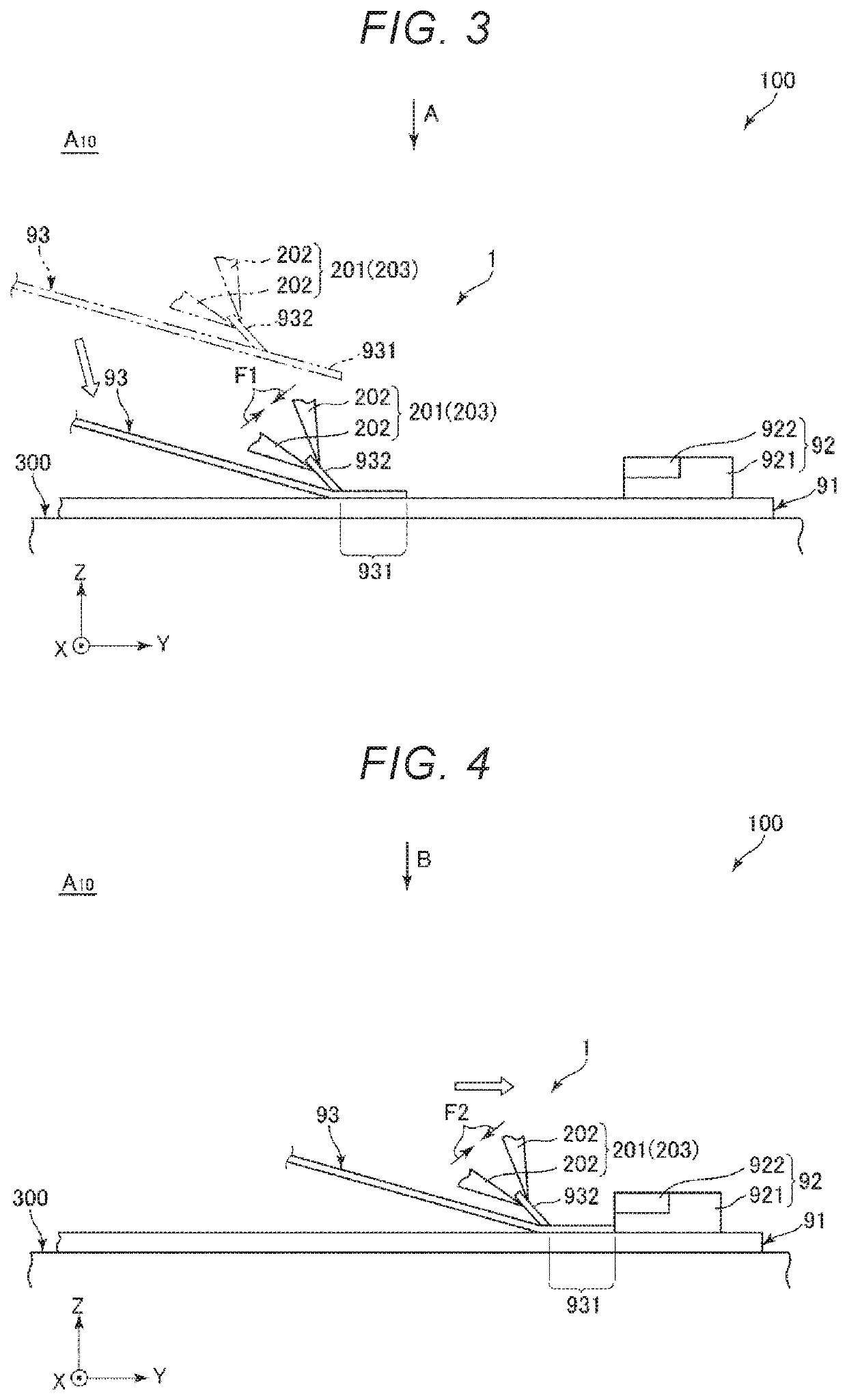
[0047]The control apparatus 200 is placed apart from the robot 1 and includes a computer with a CPU (Central Processing Unit) as an example of a processor provided inside etc. The robot system 100 may perform coupling work of coupling a flexible cable 93 to a connector 92 provided on a board 91.

[0048]The robot 1 has a base 11 and a movable unit 10.

[0049]The base 11 is a support that supports the movable unit 10 drivably from below, and fixed to e.g. a floor within a factory. In t...

second embodiment

[0179]As below, the second embodiment of the robot system and the coupling method according to the present disclosure will be explained with reference to FIGS. 31 to 33 with a focus on the differences from the above described embodiment, and the explanation of the same items will be omitted.

[0180]In the embodiment, for adjustment of the action conditions including action speeds of the robot 1, a menu setting window 37 shown in FIG. 31, a sixth setting window 38 shown in FIG. 32, and a seventh window 39 shown in FIG. 33 are appropriately displayed on the display unit 401. The configuration having these windows is effective for smooth and prompt coupling work when the height of the coupling end portion 931 of the cable 93 relative to the board 91 is unstable, that is, when the flexure of the coupling end portion 931 is non-negligible for coupling work.

[0181]As shown in FIG. 31, the menu setting window 37 contains a sixth item 371 for “STEP6 Creation of Contact Action”, a seventh item ...

modified example 1

[0201]FIG. 35 is a block diagram showing modified example 1 with a focus on hardware of a robot system.

[0202]FIG. 35 shows an overall configuration of a robot system 100B in which a computer 63 is directly coupled to the robot 1. The control of the robot 1 is directly executed by reading commands in a memory using a processor in the computer 63.

[0203]Therefore, the computer 63 may be regarded as “control apparatus 200”.


PUM


Abstract

A robot system that performs work of coupling a flexible cable to a connector provided on a board, includes a robot in which a gripping unit that grips the cable and a force detection unit that detects a force acting on the gripping unit are provided, a control unit that controls the robot to perform a conveyance action to grip the cable using the gripping unit and convey the cable onto the board, and an insertion action to insert the cable into the connector by force control based on a detection result in the force detection unit, an insertion speed entry part in which an insertion speed of the cable into the connector at the insertion action is entered, and a determination unit that can determine force control information necessary for the force control in the insertion action according to the insertion speed.

Description

[0001]The present application is based on, and claims priority from, JP Application Serial Number 2018-230437, filed Dec. 7, 2018, the disclosure of which is hereby incorporated by reference herein in its entirety.BACKGROUND1. Technical Field[0002]The present disclosure relates to a robot system and coupling method.2. Related Art[0003]For example, JP-A-2010-69587 discloses a robot system including an articulated robot and a controller that controls the articulated robot. The robot of the robot system described in JP-A-2010-69587 has a distal end portion to which an end effector that grips a cable is attached. The robot may perform coupling work of inserting and coupling the cable gripped by the end effector into a connector under a force control condition.[0004]Generally, it is known that work of creating a control program for execution of force control requires skill. Accordingly, for example, for changing the control program, the changing work is not easy depending on the contents...

Claims


Application Information

Patent Timeline
Patent Type & Authority Applications(United States)
IPC IPC(8): B25J9/16B25J15/00B25J9/10
CPCB25J9/1687B25J9/1015B25J9/1633B25J15/0004B25J9/1697B25J9/0081B25J9/1656B25J9/1602B25J9/08B25J17/00B25J18/00G05B2219/40584G05B2219/40028G05B2219/45033G05B2219/45097H01R12/592H01R43/00H01R43/28
Inventor UEDA, JUNYA
Owner SEIKO EPSON CORP
Learn More