Vehicle control device
a technology of vehicle control and control device, which is applied in the direction of control device, external condition input parameters, vehicle components, etc., can solve problems such as uneasy driving
- Summary
- Abstract
- Description
- Claims
- Application Information
AI Technical Summary
Benefits of technology
Problems solved by technology
Method used
Image
Examples
first modification example
[0248]A vehicle control device (hereinafter, referred to as “a first modification device”) according to a first modification example of the present control device will next be described. The first modification device differs from the present control device in that the first modification device makes the timing at which the second speed management control is started earlier than the timing at which the first speed management control should be started, and makes the timing at which the second speed management control is ended later than the timing at which the first speed management control should be ended.
[0249]The CPU of the DSECU 10 the first modification device executes the substantially same routines as the routines executed by the CPU of the DSECU 10 of the present control device. Note, however that, the CPU of the first modification device executes a routine which is obtained by modifying a part of the routine shown in FIG. 6 as follows. Furthermore, as represented by a broken ...
second modification example
[0283]A vehicle control device (hereinafter, referred to as “a second modification device”) according to a second modification example of the present control device will next be described. The second modification device differs from the present control device in that the second modification device enables / allows the driver to customize an allowable quickness degree in movement of the vehicle VA in the first speed management control and the second speed management control.
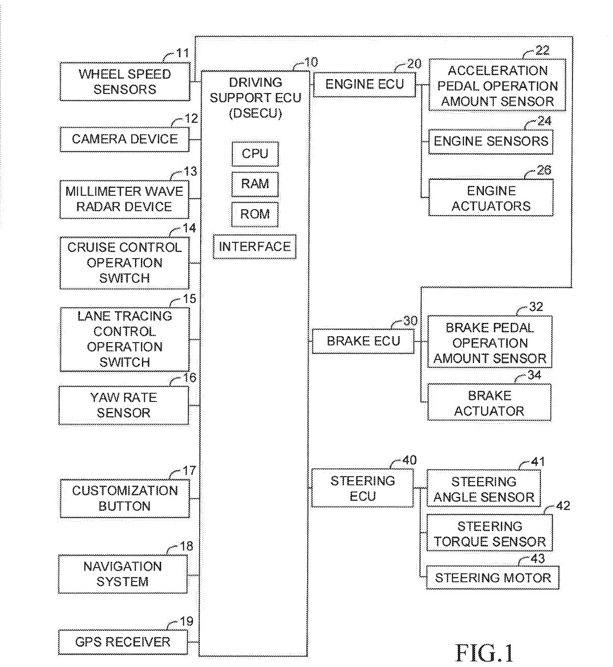
[0284]The second modification device uses a first customization lateral G (R)′ map (referring to FIG. 11) and a second customization lateral G(R)′ map (referring to FIG. 11) in addition to the first lateral G(R) map and the second lateral G(R) map. These maps have been stored in the ROM of the DSECU 10, as other maps described in the present specification.
[0285]As shown in FIG. 11, the upper limit lateral G which is acquired / determined according to the first customization lateral G(R)′ map is smaller than the upper ...
third modification example
[0309]A vehicle control device (hereinafter, referred to as “a third modification device”) according to a third modification example will next be described.
[0310]The third modification differs from the present control device in the following point.
[0311]When information on surroundings of the vehicle VA in the vehicle width direction satisfies a predetermined condition (a specific condition), the third modification device modifies the upper limit lateral G or the like in such a manner that the upper limit lateral G or the like become smaller than those used when the information on the surroundings does not satisfy the predetermined condition. The predetermined condition is satisfied when the information on the surroundings indicates that the surroundings are as such that cause the driver to easily feel uneasy.
[0312]The CPU of the DSECU 10 of the third modification device executes a routine represented by a flowchart shown in FIG. 13 in addition to the routines shown in FIG. 4 throug...
PUM
 Abstract
Description
Claims
Application Information
 - R&D
- Intellectual Property
- Life Sciences
- Materials
- Tech Scout
- Unparalleled Data Quality
- Higher Quality Content
- 60% Fewer Hallucinations
Browse by: Latest US Patents, China's latest patents, Technical Efficacy Thesaurus, Application Domain, Technology Topic, Popular Technical Reports.
© 2025 PatSnap. All rights reserved.Legal|Privacy policy|Modern Slavery Act Transparency Statement|Sitemap|About US| Contact US: help@patsnap.com


