
Imaging device, camera-equipped drone, and mode control method, and program

Inactive Publication Date: 2020-06-11
SONY CORP
View PDF0 Cites 3 Cited by
  • Summary
  • Abstract
  • Description
  • Claims
  • Application Information

AI Technical Summary

Benefits of technology

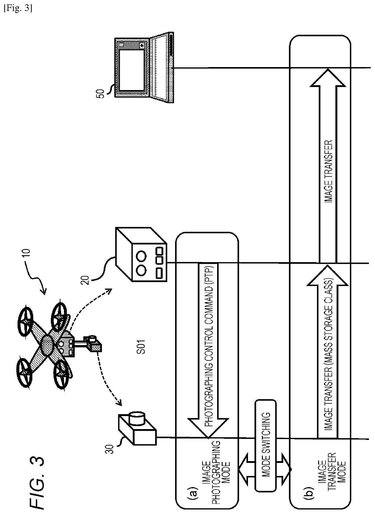
The present patent provides a configuration for a device that can switch between an image photographing mode and an image transfer mode based on a specific condition. In the image photographing mode, communication is performed using a PTP protocol with a connected drone main body control device. In the image transfer mode, communication is performed using an MSC protocol with the connected drone main body control device. This configuration allows for seamless switching between the two modes and ensures efficient data transfer.

Problems solved by technology

However, in both cases, the above process is to acquire and check the photographed images after the drone returns to the ground, and for example, it is difficult to check whether or not a desired image has been photographed at the time of image photographing.
As described above, when the process of acquiring and checking the photographed images is performed after the drone returns to the ground, in a case where a desired image fails to be photographed, there is a problem in that it is necessary to perform rephotographing, and loss of time and cost increase are caused.
However, if an image transfer is executed using a PTP communication protocol while performing photographing control according to PTP communication which is the USB communication standard between the drone main body controller and the camera, an image transfer time from the camera to the drone main body controller increases, and the photographing control command is unable to be issued during that time, and thus there occurs a problem in that photographing control is obstructed.

Method used


Image

  • Imaging device, camera-equipped drone, and mode control method, and program
  • Imaging device, camera-equipped drone, and mode control method, and program
  • Imaging device, camera-equipped drone, and mode control method, and program

Examples


Embodiment Construction

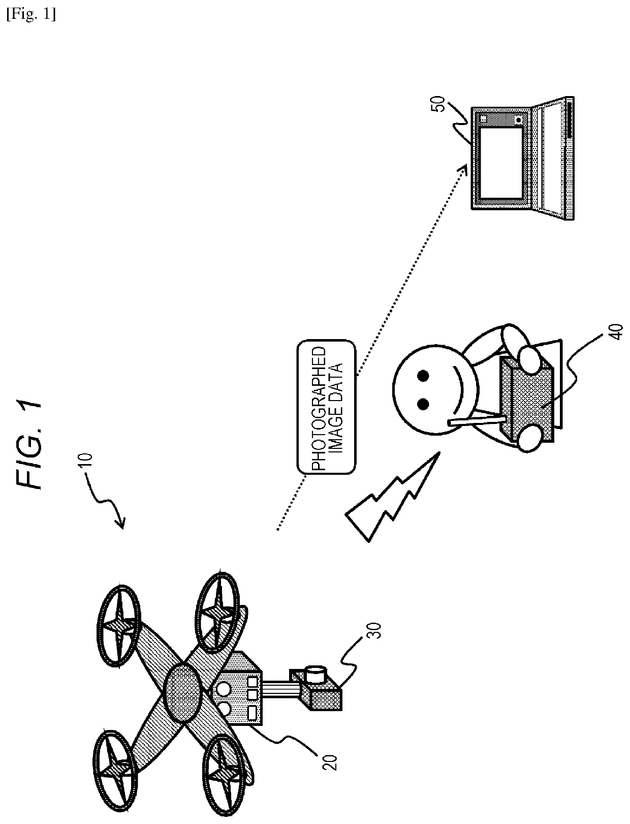
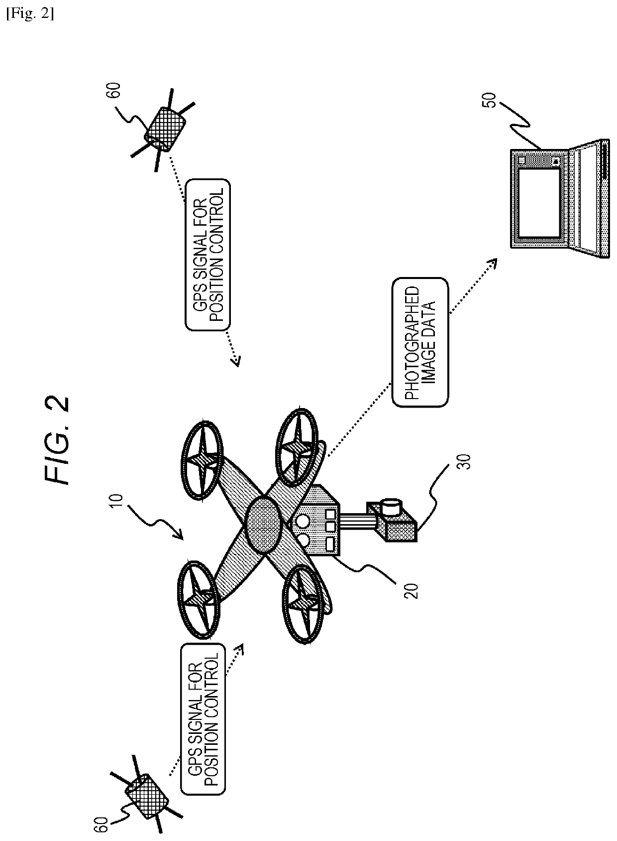
[0054]An imaging device, a camera-equipped drone, a mode control method, and a program of the present disclosure will be described below in detail with reference to the appended drawings. Further, the description will proceed in accordance with the following items.

[0055]1. Configuration example of system which process of present disclosure can be applied

[0056]2. Configuration example of drone main body control device and camera

[0057]3. Specific example of switching process between image photographing mode and image transfer mode

[0058]4. Setting of mode switching condition according to various photographing situations and specific example of mode switching process

[0059]4-1. (First process example) process example in which moving speed and photographing process stop period are used as mode switching determination condition

[0060]4-2. (Second process example) process example in which current position and photographing process stop period are used as mode switching determination conditio...


PUM


Abstract

An imaging device for use on-board a reconnaissance vehicle comprises an image capturing unit configured to capture images of a photographic area. A control unit communicates via a serial communications interface with a control body unit of the reconnaissance vehicle, and operates in an image photographing mode that receives control information from the control body unit of the reconnaissance vehicle via the serial communications interface and in an image transfer mode that transfers the images to the control body unit of the reconnaissance vehicle via the serial communications interface in accordance with a data transfer protocol. The control unit responds to detecting mode switching conditions to switch autonomously from the image photographing mode to the image transfer mode. Only a single serial communications interface is needed both to control the imaging device and to transfer the captured images from the imaging device in the image transfer mode.

Description

CROSS REFERENCE TO RELATED APPLICATIONS[0001]This application claims the benefit of Japanese Priority Patent Application JP 2017-131674 filed on Jul. 5, 2017, the entire contents of which are incorporated herein by reference.TECHNICAL FIELD[0002]The present disclosure relates to an imaging device imaging device, such as a camera or the like, for use on-board a reconnaissance vehicle, such as a drone or remote controlled vehicle, a camera-equipped drone, a method, and a program. More particularly, the present disclosure relates to an imaging device, a camera-equipped drone, a mode control method, and a program which are capable of performing switching between an image photographing mode and an image transfer mode.BACKGROUND ART[0003]In recent years, the use of reconnaissance vehicles such as drones which are compact air vehicles which performs remote controlled flight or autonomous flight based on a GPS or the like has been rapidly increasing.[0004]For example, a drone is equipped wi...

Claims


Application Information

Patent Timeline
IPC IPC(8): B64C39/02G05D1/00H04L29/08H04N1/00
CPCG05D1/0094B64C2201/127G05D1/0022B64C39/024H04L67/06H04N1/00204G05D1/0038H04N7/185B64U2101/31G03B15/006H04N23/667B64U2101/30
Inventor HARADA, TAKESHIODA, RYUNOSUKE
Owner SONY CORP
Learn More