Device for inductively charging an electronic element of the mobile-phone type

a mobile phone and electronic element technology, applied in mechanical devices, transportation and packaging, gearing, etc., can solve the problems of increasing the price of the recharging device, and affecting the charging efficiency of the mobile phone. , to achieve the effect of increasing the charging area

Active Publication Date: 2020-06-11
CONTINENTAL AUTOMOTIVE FRANCE +1
View PDF0 Cites 0 Cited by
  • Summary
  • Abstract
  • Description
  • Claims
  • Application Information

AI Technical Summary

Benefits of technology

[0024]According to a third embodiment of the invention, the main element is a driving eccentric wheel, the actuating mechanism also comprising a guide finger and an auxiliary eccentric wheel not directly driven by the motor, the actuating mechanism being configured in such a way that the movement of the stage is a combination of a translational movement and of a rotational movement. This combined translational and rotational movement of the stage allows a larger charging area to be covered.

Problems solved by technology

Deviations, even small deviations, from the optimal position may lead to low recharging efficiency.
This is particularly true of a motor vehicle in which the mobile phone is liable to be poorly positioned or to move.
Using two electric motors does, however, considerably increase the price of the recharging device and increases its bulk, given that each motor has its own control electronics, which are therefore duplicated.
As an alternate solution, provision has also been made for the number of emitting antennas to be multiplied, something which is likewise a costly and complex solution.

Method used


Image

  • Device for inductively charging an electronic element of the mobile-phone type
  • Device for inductively charging an electronic element of the mobile-phone type
  • Device for inductively charging an electronic element of the mobile-phone type

Examples


first embodiment

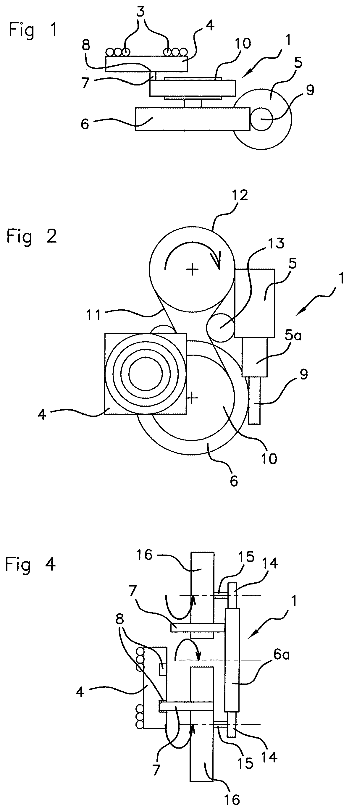
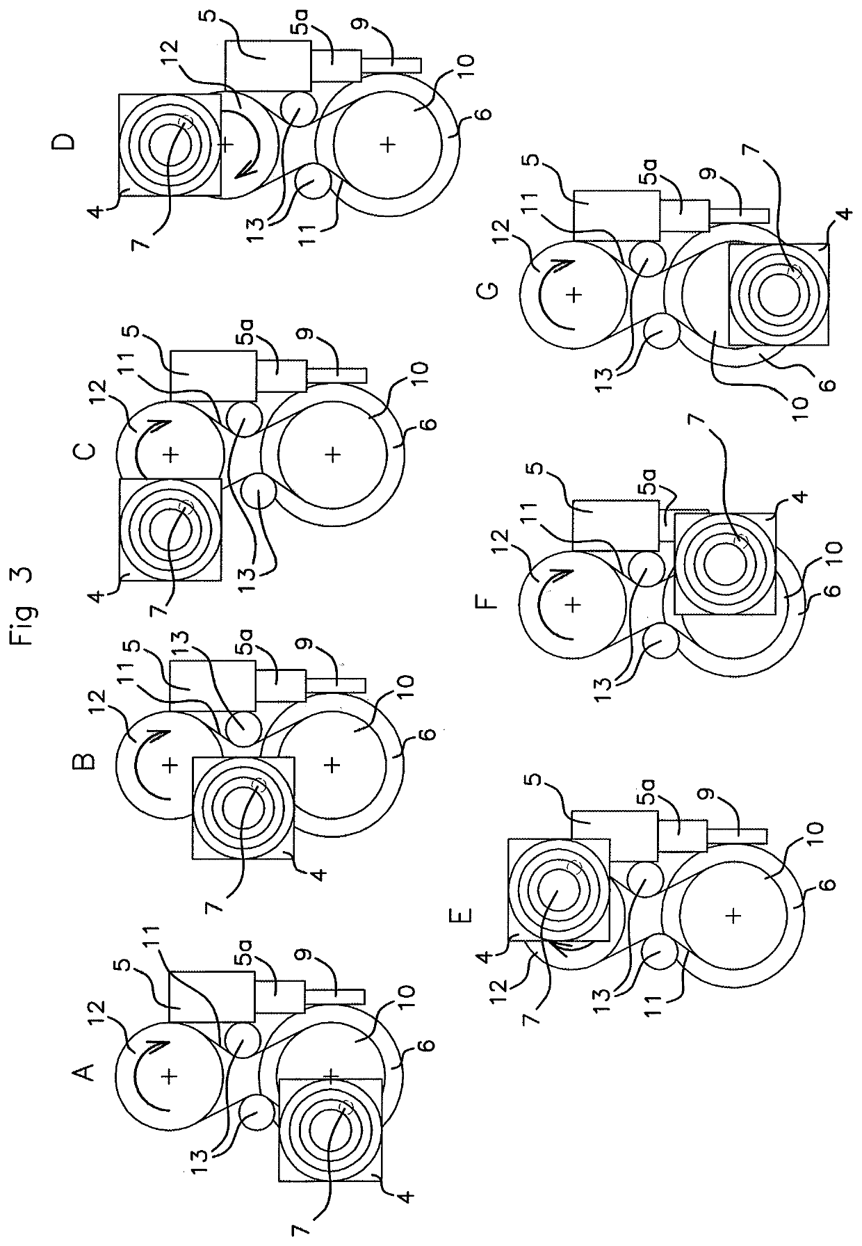
[0047]In a first embodiment, with reference notably to FIGS. 1 to 3A-3G, in the actuating mechanism, the main drive element 6, in direct mesh with the motor 5 at its periphery, is secured to a pulley by way of driving pulley 10.

[0048]This driving pulley 10 may be positioned coaxially with respect to the main drive element 6 and is driven in rotation by the motor 5 via the main drive element 6. A belt 11 is then wrapped around the driving pulley 10 and around at least one driven return pulley 12. It is this belt 11 that bears said at least one guide finger 7 entering a groove 8 made on a face of the stage 4 facing the actuating mechanism and the drive element 6. FIGS. 1 to 3A-3G show a single guide finger 7.

[0049]In FIG. 1, the guide finger 7 is in the form of an angle bracket. The pulleys 10, 12 drive the belt 11 in rotation. The actuating mechanism may comprise at least one tensioning roller 13 for tensioning the belt 11, advantageously two tensioning rollers. The tensioning the ro...

second embodiment

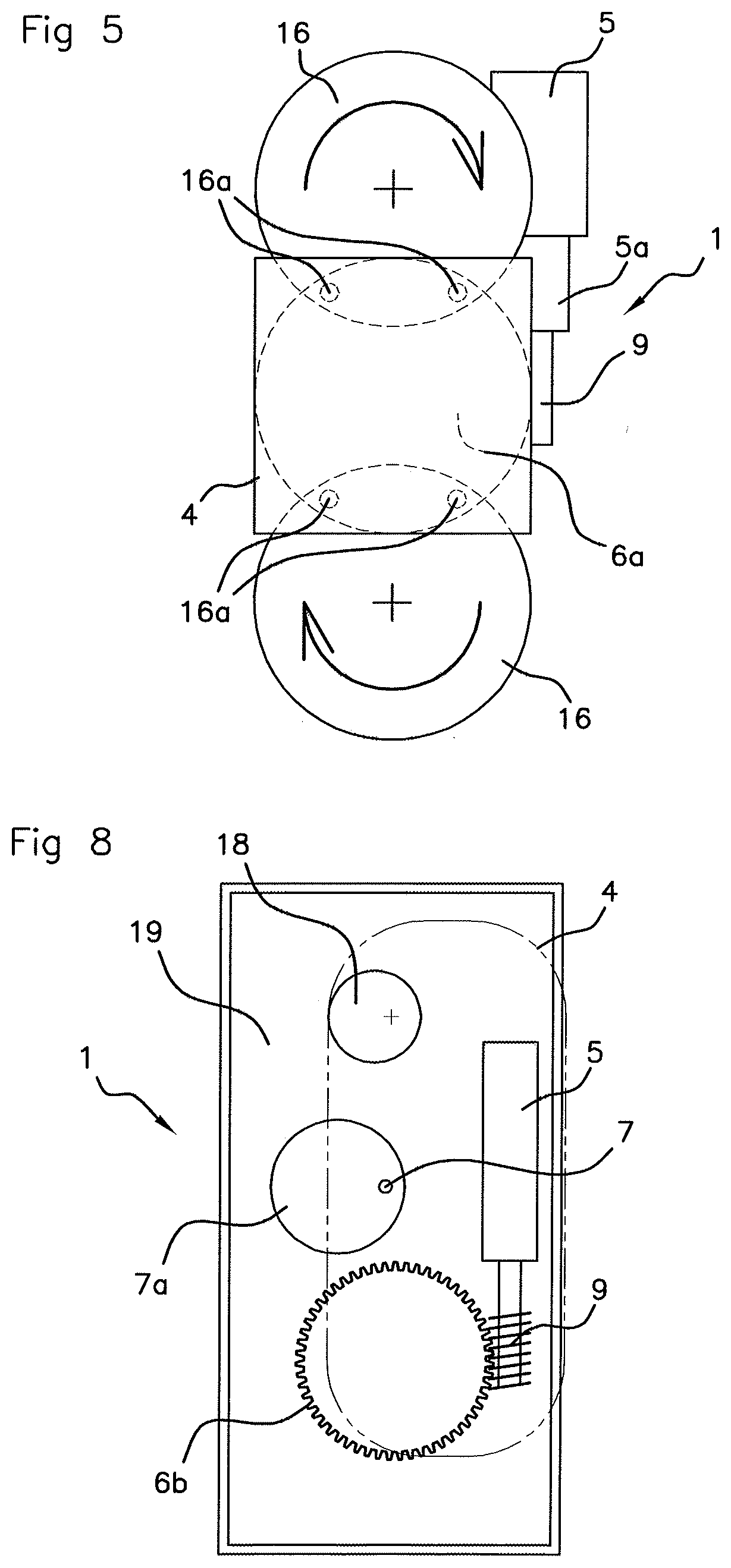
[0051]In the invention, with reference notably to FIGS. 4 to 7, in the actuating mechanism, the main drive element, in direct mesh with the motor 5 at its periphery, is a primary meshing element 6a driving two secondary meshing elements 14, 15, 16 positioned so that they are diametrically opposite each other with respect to the center of the primary meshing element 6a.

[0052]The guide finger(s) 7, of which there are advantageously two per secondary meshing set 14, 15, 16, as shown in FIGS. 4 to 7H, may pass through each secondary meshing element 14, 15, 16 in the direction of the stage 4. The guide finger(s) 7 may be mobile toward and away from the stage 4 through the action of the cam profile 7 borne by one face of the primary meshing element 6a facing toward the stage 4.

[0053]The guide finger(s) 7 may be pushed toward the stage 4 by the cam profile 17 notably visible in FIGS. 4 and 7. The guide finger(s) 7 may point in a manner perpendicular to their associated secondary meshing s...

third embodiment

[0060]In the invention, with reference notably to FIGS. 8 to 11, in the actuating mechanism, the drive element, in direct mesh with the motor 5 at its periphery, is a driving eccentric wheel 6b. The actuating mechanism also comprises a guide finger 7 and an auxiliary eccentric wheel 18 not directly driven by the motor 5. The actuating mechanism is configured in such a way that the movement of the stage 4 is a combination of a translational movement and of a rotational movement.

[0061]The driving eccentric wheel 6b may be toothed and collaborate with a meshing surface provided on the output shaft 9 of the motor 5. A guide zone 7a, advantageously with a circular closed edge, delimits the path of the guide finger 7. The guide finger 7, which may be of substantially rectilinear shape, may have a first end housed in the groove of the stage 4, and a second end flanked by the guide zone 7a. The movement of the stage 4 is defined by the closed circular edge of the guide zone 7a, against whic...


PUM


Abstract

A device for the inductive recharging of an electronic element of the mobile-phone or digital tablet type having at least one receiving antenna. The device having an exterior face intended to support the electronic element, a stage of planar shape being able to move inside the device and bearing at least one emitting antenna intended to be aligned with, and in close proximity to, the at least one receiving antenna, the mobile stage being actuated by a motorized actuating mechanism. The actuating mechanism includes a single motor coupled to a main drive element that renders the stage mobile in a plane parallel to the exterior face of the device, the main drive element being circular in shape, and the motor meshing with a periphery of the main drive element and driving the main drive element in rotation.

Description

CROSS REFERENCE TO RELATED APPLICATIONS[0001]This application is the U.S. National Phase Application of PCT International Application No. PCT / EP2017 / 053247, filed Nov. 24, 2017, which claims priority to French Patent Application No. 1661535, filed Nov. 25, 2016, the contents of such applications being incorporated by reference herein.FIELD OF THE INVENTION[0002]The present invention relates to a device for the inductive recharging of an electronic element of the mobile-phone or digital tablet type having at least one receiving antenna. The device has an exterior face intended to support the electronic element for the recharging of same. A stage of planar shape is able to move inside the device while bearing at least one emitting antenna intended to be aligned with, and in close proximity to, said at least one receiving antenna, the mobile stage being actuated by a motorized actuating mechanism.[0003]Such an inductive charging device can be carried on board a motor vehicle, although ...

Claims


Application Information

Patent Timeline
Patent Type & Authority Applications(United States)
IPC IPC(8): H02J50/90H02J50/10H02J50/00H02J50/40B60R11/02B60R16/03
CPCH02J50/90H02J50/402B60R11/0241B60R16/03H02J50/005H02J50/10H02K7/1004H01F38/14F16H1/04F16H21/18H01F2017/0073
Inventor LUBERT, VINCENTDUCOS, FRÉDÉRIC
Owner CONTINENTAL AUTOMOTIVE FRANCE
Why Eureka
Try Eureka