A portable solar umbrella

A solar energy and portable technology, applied in the field of umbrellas, can solve the problems of insufficient power supply for fans or LED lights, the reduction of the charging area of ​​solar panels, and the easy damage of solar panels, so as to improve the safety of use, compact structure, increase The effect of a large charging area

Active Publication Date: 2018-08-28
济宁高新科达科技项目服务有限公司
View PDF5 Cites 0 Cited by
  • Summary
  • Abstract
  • Description
  • Claims
  • Application Information

AI Technical Summary

Problems solved by technology

However, at present, the solar panels of solar umbrellas are generally distributed on the umbrella surface to increase the area where the solar panels are exposed to sunlight. Although this method is conducive to increasing the charging area of ​​the solar panels, they are installed on the umbrella surface It is inconvenient to store the sun umbrella, and when the umbrella surface is impacted or the umbrella falls, the solar panel is easily damaged, and installing the solar panel on the top of the umbrella can solve the storage problem of the sun umbrella and alleviate the easy damage of the solar panel However, this method cannot fundamentally solve the problem of solar energy being damaged by external forces, and this method will greatly reduce the charging area of ​​the solar panel, which is not enough to provide the power required by the fan or LED lights
[0004] Moreover, most of the fans installed on the umbrella are directly formed small fans or fan blades installed on the umbrella stand or umbrella pole. No matter the small fan or the fan blades are self-contained and cannot be received in the umbrella, making The umbrella is not stored, or the fan is disassembled when it is stored, which is troublesome and not easy to carry around

Method used


Image

  • A portable solar umbrella
  • A portable solar umbrella
  • A portable solar umbrella

Examples


Embodiment Construction

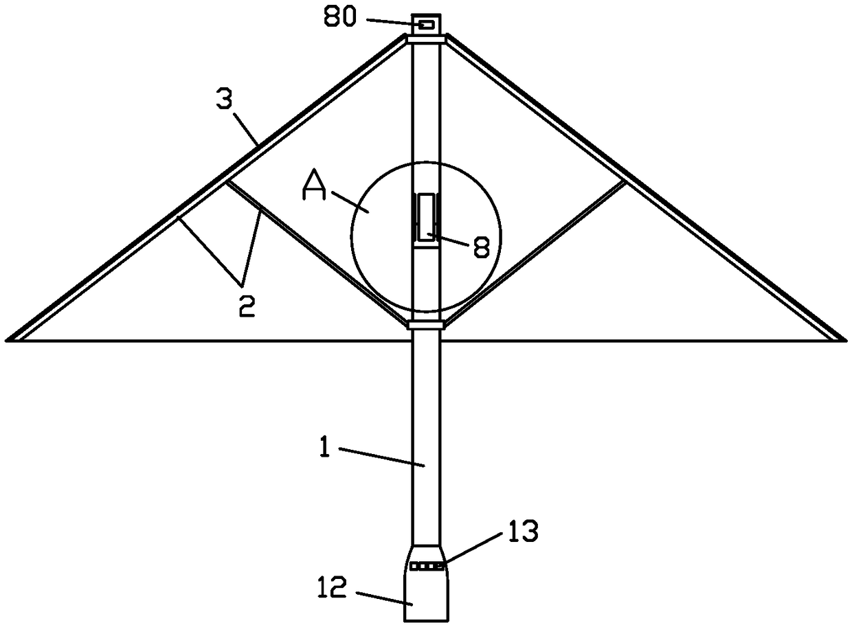
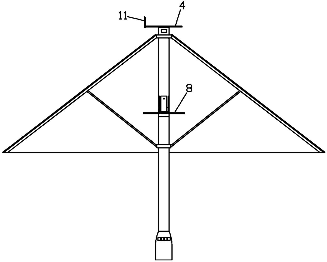
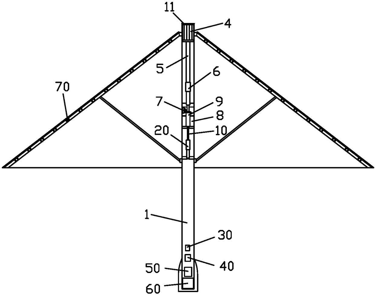
[0030] see Figure 1 to Figure 6 , In a preferred embodiment of the present invention, a portable solar umbrella includes an umbrella pole 1 , an umbrella stand 2 mounted on the umbrella pole 1 and an umbrella surface 3 covering the umbrella stand 2 . The umbrella pole 1 is hollow, and a solar panel 4, a first transmission device 5, a first drive device 6, a second drive device 7, a second transmission device 9 and a charging device are sequentially housed in it from top to bottom. The battery 60 is mounted with an acceleration sensor 30 , a photosensitive sensor 80 , a controller 50 and a fan unit 8 . The solar panel 4 is located at the top of the umbrella pole 1, and is slidably connected with the umbrella pole 1; the solar panel 4 is connected to the first transmission device 5, and is connected to the first driving device 6 through the first transmission device 5, and the first driving device 6 is connected to the charging device. The battery 60 , the rechargeable battery...


PUM


Abstract

The invention provides a portable solar energy umbrella and belongs to the field of umbrellas. The umbrella comprises an umbrella rod, an umbrella frame installed on the umbrella rod, and an umbrella cover covering the umbrella frame. The umbrella rod is hollow and a solar cell panel, a first transmission device, a first drive device and a rechargeable battery are arranged in the umbrella rod; the solar cell panel is located at the top end of the umbrella rod and is in slide connection with the umbrella rod; the first transmission device is connected with the solar cell panel and the first drive device separately and can be driven by the first drive device to drive the solar cell panel to slide upward to be unfolded or slide downward to be stored in the umbrella rod; the first drive device is connected with the rechargeable battery which is connected with the solar cell panel. The umbrella also comprises a controller and an acceleration sensor which are installed on the umbrella rod; the controller is connected with the acceleration sensor and the first drive device separately. The umbrella is provided with the solar cell panel which can be automatically stored in the umbrella rod; the certain charging area of the solar cell panel can be guaranteed, and the self-protectiveness of the solar cell panel is improved.

Description

【Technical field】 [0001] The invention relates to the field of umbrellas, in particular to a portable solar umbrella. 【Background technique】 [0002] From ancient times to the present, umbrellas are a tool for people to travel, and even become a kind of culture. In ancient times, there were oil-paper umbrellas, and in modern times, there are sun umbrellas and household umbrellas. Our lives are closely related to umbrellas. Ordinary umbrellas can only make the best use of them. , Sunshade or rain protection, single-function umbrellas cannot meet the needs of the public, so multi-functional umbrellas have emerged as the times require. [0003] At present, fans or LED lights are often added to umbrellas for cooling or lighting. Both fans and LED lights need to be driven by electric energy. Generally, batteries are added to umbrellas. However, under the requirements of energy depletion and "zero pollution", People apply natural solar energy to umbrellas to provide power for fan...

Claims


Application Information

Patent Timeline
Patent Type & Authority Patents(China)
IPC IPC(8): A45B3/08A45B3/00
CPCA45B3/00A45B3/08A45B2200/1027
Inventor 杨海梅
Owner 济宁高新科达科技项目服务有限公司
Why Eureka
Try Eureka