
Audio Processing Apparatus and Method Therefor

a technology of audio processing and audio, applied in the direction of electrical apparatus, stereophonic system, loudspeaker enclosure positioning, etc., can solve the problems of cumbersome and disadvantageous loudspeaker configuration, large number of loudspeakers, inconvenience perceived by consumers, etc., to facilitate implementation and/or operation, flexible positioning of loudspeakers, and increase flexibility

Active Publication Date: 2020-06-11
KONINKLJIJKE PHILIPS NV
View PDF0 Cites 1 Cited by
  • Summary
  • Abstract
  • Description
  • Claims
  • Application Information

AI Technical Summary

Benefits of technology

The invention allows for better audio rendering in various scenarios, improving the user experience. It offers increased flexibility in positioning of audio transducers (specifically loudspeakers) used for rendering audio. The approach allows for adaptive and optimum performance of audio transducers not positioned optimally while still being able to fully exploit those that are. The render controller selects the rendering mode based on a quality metric generated by a perceptual model, resulting in improved performance and adaptation in many embodiments.

Problems solved by technology

However, the requirement to use specific loudspeaker configurations with typically a relatively high number of loudspeakers is cumbersome and disadvantageous.
Indeed, a significant inconvenience perceived by consumers when deploying e.g. home cinema surround sound systems is the need for a relatively large number of loudspeakers to be positioned at specific locations.
Typically, practical surround sound loudspeaker setups will deviate from the ideal setup due to users finding it impractical to position the loudspeakers at the optimal locations.
Also, channel based audio coding systems are typically not able to cope with a different number of loudspeakers.
However the provided methods rely on either fixed reproduction setups or on unspecified syntax.
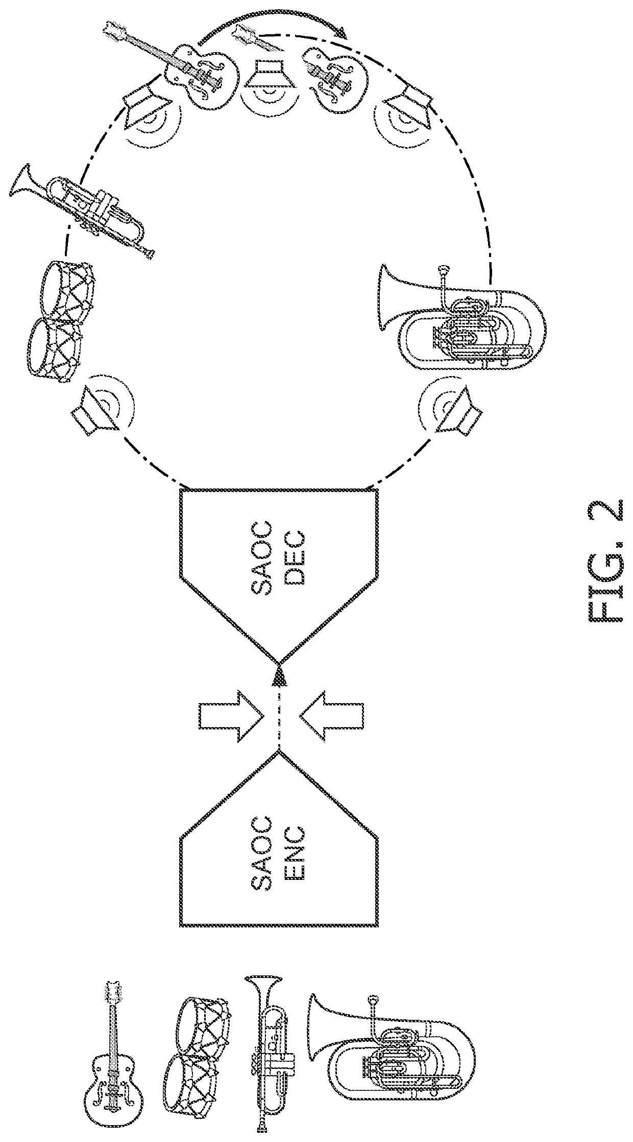
Thus SAOC does not provide normative means to fully transmit an audio scene independently of the loudspeaker setup.
Also, SAOC is not well equipped to the faithful rendering of diffuse signal components.
However, such a requirement tends to be problematic for parametric coding techniques that have been used quite heavily in the past (viz.
In particular, the compensation of information loss for the individual signals tends to not be fully compensated by the parametric data even at very high bit rates.
Indeed, the quality will be limited by the intrinsic quality of the parametric model.
In summary, the majority of existing sound reproduction systems only allow for a modest amount of flexibility in terms of loudspeaker set-up.
Because almost every existing system has been developed from certain basic assumptions regarding either the general configuration of the loudspeakers (e.g. loudspeakers positioned more or less equidistantly around the listener, or loudspeakers arranged on a line in front of the listener, or headphones), or regarding the nature of the content (e.g. consisting of a small number of separate localizable sources, or consisting of a highly diffuse sound scene), every system is only able to deliver an optimal experience for a limited range of loudspeaker configurations that may occur in the rendering environment (such as in a user's home).

Method used


Image

  • Audio Processing Apparatus and Method Therefor
  • Audio Processing Apparatus and Method Therefor
  • Audio Processing Apparatus and Method Therefor

Examples


Embodiment Construction

[0076]The following description focuses on embodiments of the invention applicable to a rendering system arranged to render a plurality of rendering audio components of different types, and in particular to rendering of audio channels, audio objects and audio scene objects of an MPEG audio stream. However, it will be appreciated that the invention is not limited to this application but may be applied to many other audio rendering systems as well as other audio streams.

[0077]The described rendering system is an adaptive rendering system capable of adapting its operation to the specific audio transducer rendering configuration used, and specifically to the specific positions of the audio transducers used in the rendering.

[0078]The majority of existing sound reproduction systems only allow a very modest amount of flexibility in the loudspeaker set-up. Due to conventional systems generally being developed with basic assumptions regarding either the general configuration of the loudspeak...


PUM


Abstract

An audio processing apparatus comprises a receiver (705) which receives audio data including audio components and render configuration data including audio transducer position data for a set of audio transducers (703). A renderer (707) generating audio transducer signals for the set of audio transducers from the audio data. The renderer (7010) is capable of rendering audio components in accordance with a plurality of rendering modes. A render controller (709) selects the rendering modes for the renderer (707) from the plurality of rendering modes based on the audio transducer position data. The renderer (707) can employ different rendering modes for different subsets of the set of audio transducers the render controller (709) can independently select rendering modes for each of the different subsets of the set of audio transducers (703). The render controller (709) can select the rendering mode for a first audio transducer of the set of audio transducers (703) in response to a position of the first audio transducer relative to a predetermined position for the audio transducer. The approach may provide improved adaptation, e.g. to scenarios where most speakers are at desired positions whereas a subset deviate from the desired position(s).

Description

CROSS-REFERENCE TO PRIOR APPLICATIONS[0001]This application is a divisional application of U.S. Ser. No. 14 / 786,567 filed Oct. 23, 2015 which is the U.S. National Phase application under 35 U.S.C. § 371 of International Application No. PCT / EP2014 / 060109, filed on May 6, 2014, which claims the benefit of European Patent Application No. 13168064.7, filed on May 16, 2013. These applications are hereby incorporated by reference herein.FIELD OF THE INVENTION[0002]The invention relates to an audio processing apparatus and method therefor, and in particular, but not exclusively, to rendering of spatial audio comprising different types of audio components.BACKGROUND OF THE INVENTION[0003]In recent decades, the variety and flexibility of audio applications has increased immensely with e.g. the variety of audio rendering applications varying substantially. On top of that, the audio rendering setups are used in diverse acoustic environments and for many different applications.[0004]Traditional...

Claims


Application Information

Patent Timeline
Patent Type & Authority Applications(United States)
IPC IPC(8): H04S7/00H04R5/02
CPCH04S7/308H04S2400/11H04S2420/13H04R2205/024H04S2420/11H04S2420/01H04R2420/03H04R5/02H04S7/40H04S2400/15H04S7/302H04S7/301H04S7/00
Inventor DE BRUIJN, WERNER PAULUS JOSEPHUSHARMA, AKI SAKARIOOMEN, ARNOLDUS WERNER JOHANNES
Owner KONINKLJIJKE PHILIPS NV
Learn More