
Surgical robot

A surgical robot and surgical instrument technology, applied in the field of surgical robots, can solve the problems of reduced surgical accuracy, easy fatigue of doctors, low flexibility, etc., to reduce the risk of damage and increase the degree of freedom and flexibility.

Pending Publication Date: 2020-05-05
CHENGDU BORNS MEDICAL ROBOTICS INC
View PDF0 Cites 0 Cited by
  • Summary
  • Abstract
  • Description
  • Claims
  • Application Information

AI Technical Summary

Problems solved by technology

[0002] In minimally invasive surgery, doctors often need to manually cut, strip, and suture tissues. For some complicated surgical operations, doctors need to stand for a long time and hold micro-surgical instruments for surgery. Doctors are prone to fatigue, which affects the operation. quality
At the same time, conventional minimally invasive surgical instruments are simple imitations of traditional open surgical instruments, with less freedom, low flexibility, and high internal friction, which will lead to attenuation of transmission force and fatigue of doctors, making it difficult to avoid hand tremors, The accuracy of the operation is reduced due to fatigue, which is not convenient for the smooth operation of the operation
[0003] At present, robot-assisted minimally invasive surgery is gradually applied to actual clinical practice. Some of these robot-assisted surgery have a low degree of freedom. For example, when performing more complex minimally invasive surgery, doctors cannot The requirements for the degree of freedom, flexibility and sensitivity of surgical instruments, so there is a technical problem of inflexibility in robotic surgical operations in the prior art

Method used


Image

  • Surgical robot
  • Surgical robot
  • Surgical robot

Examples


Embodiment Construction

[0029] The present invention will be further described below in conjunction with accompanying drawing.

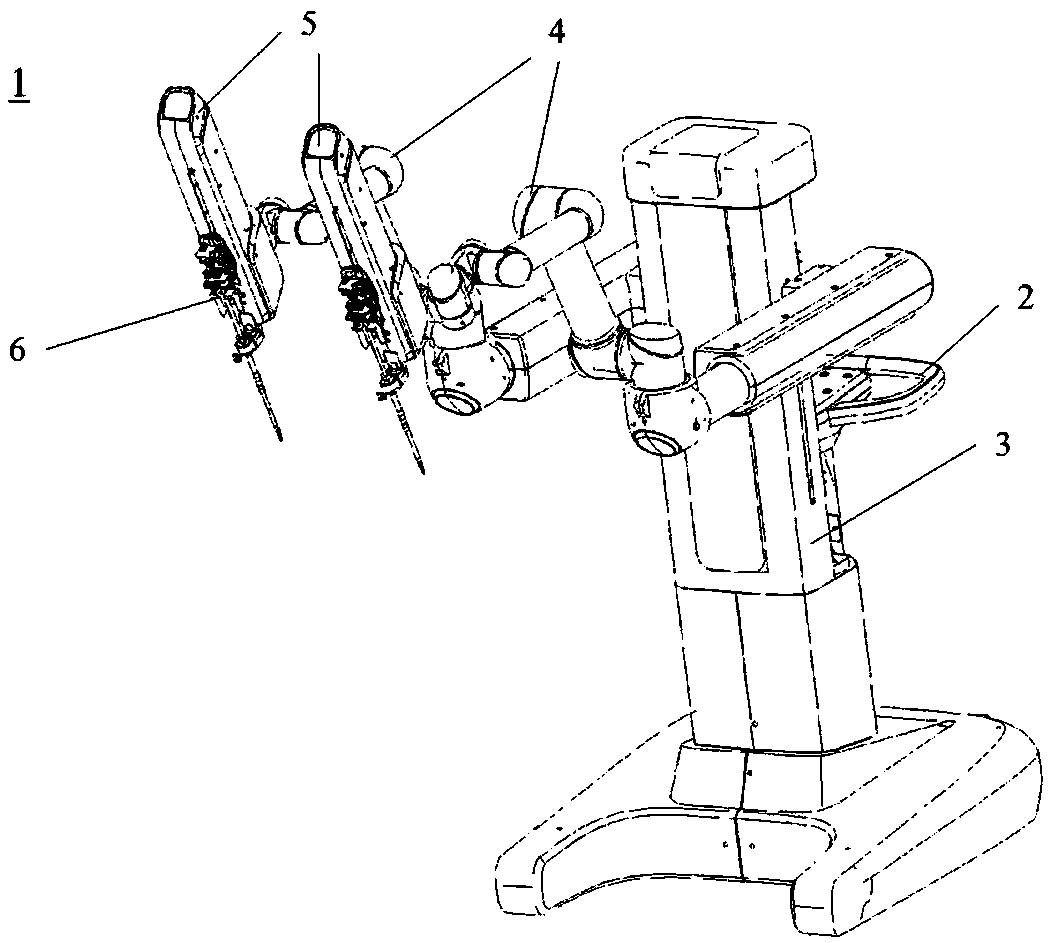
[0030] Such as figure 1 As shown, the surgical robot 1 includes a pusher 2 , a trolley 3 , a mechanical arm 4 , a slide 5 and a surgical instrument assembly 6 .

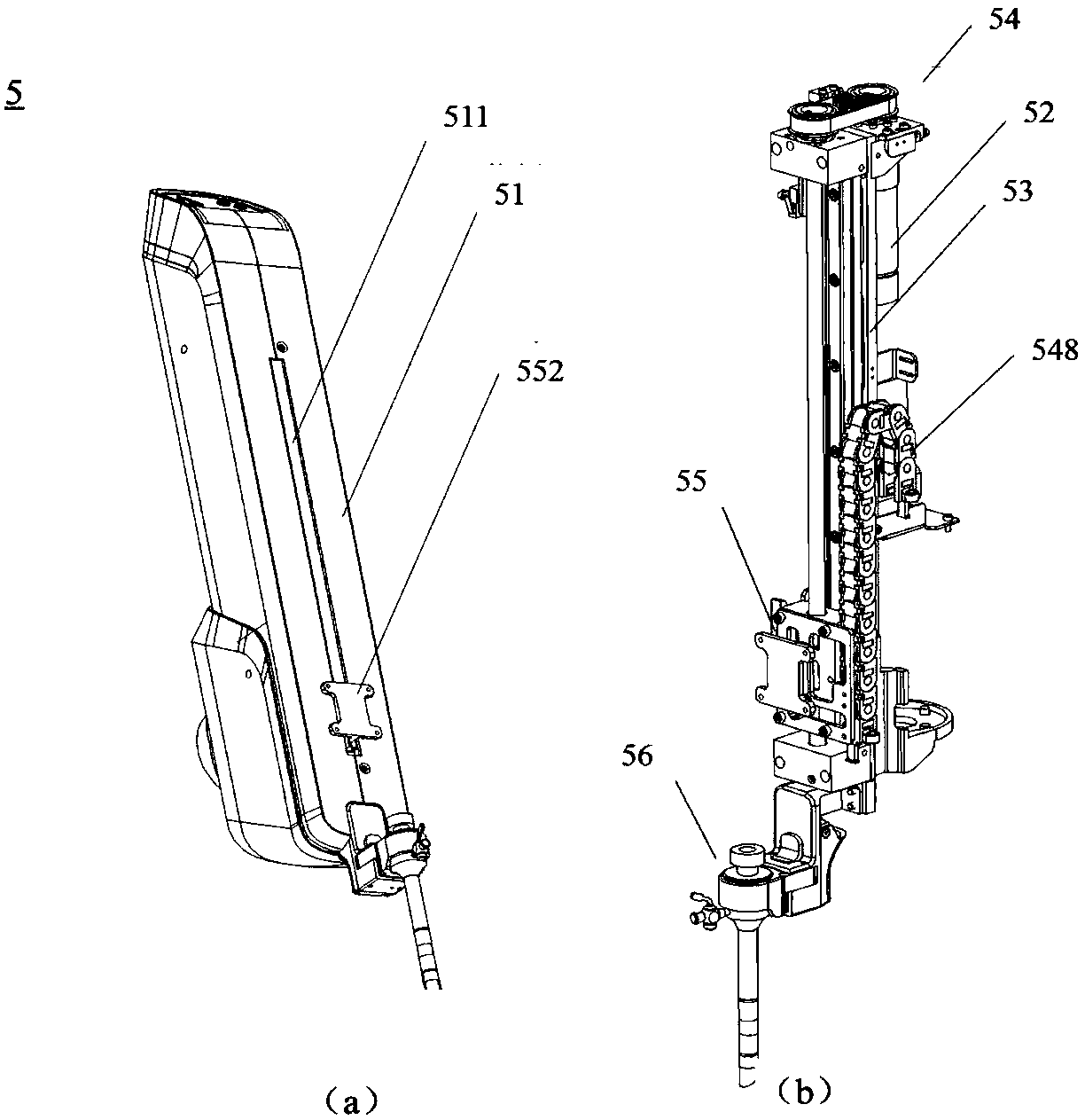
[0031] Such as figure 2 As shown in (a) and (b), the slide table 5 is composed of a housing 51, a driving motor 52, a mounting plate 53, a transmission part 54, a surgical instrument assembly connecting support 55 and a poking mechanism 56, wherein the transmission part 54 includes a driving wheel 541, a driven wheel 542, a synchronous belt 543, a bracket 544, a lead screw pair 545, and the lead screw pair 545 includes a lead screw 546 and a first slide block 547.

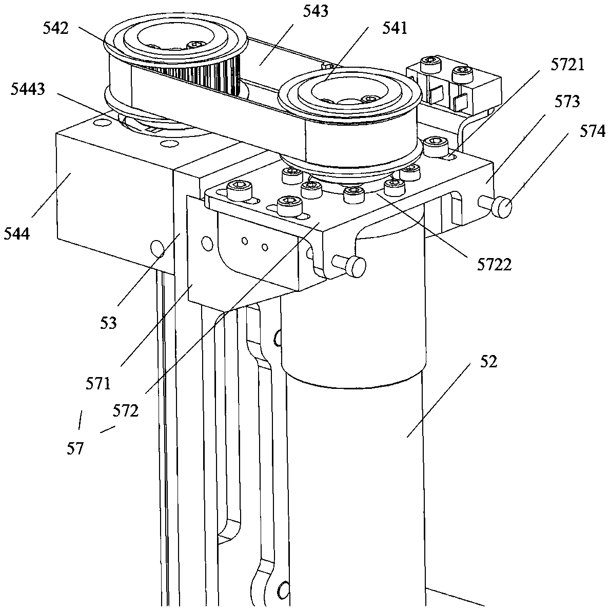
[0032] Such as figure 2 (a), (b) and image 3 As shown, the driving motor 52 is preferably provided with an encoder, and the driving motor 52 is arranged on the front of the mounting plate 53 through a driving motor fixing member 57 along the len...


PUM


Abstract

The application provides a surgical robot. The surgical robot comprises a push handle, a trolley, mechanical arms, surgical instrument assemblies and slipways used for connecting the mechanical arms with the surgical instrument assemblies correspondingly; each surgical instrument assembly includes an instrument fixing device and a surgical instrument; each slipway includes a limiting assembly usedfor limiting the moving range of the corresponding surgical instrument in a slipway direction; and each surgical instrument can do opening-closing movement. The rectilinear movement of each surgicalinstrument along the corresponding slipway can be limited through the corresponding limiting assembly, so that the situation that each surgical instrument moves to a limit position is prevented to lower the risk of damage; and each surgical instrument of the surgical robot can do deflection movement and the opening-closing movement, and thereby, the freedom degree and the flexibility of each surgical instrument are increased, and control of a doctor is more facilitated to perform surgery.

Description

technical field [0001] The invention relates to the technical field of medical instruments, in particular to a surgical robot. Background technique [0002] In minimally invasive surgery, doctors often need to manually cut, strip, and suture tissues. For some complicated surgical operations, doctors need to stand for a long time and hold micro-surgical instruments for surgery. Doctors are prone to fatigue, which affects the operation. quality. At the same time, conventional minimally invasive surgical instruments are simple imitations of traditional open surgical instruments, with less freedom, low flexibility, and high internal friction, which will lead to attenuation of transmission force and fatigue of doctors, making it difficult to avoid hand tremors, The reduction of the accuracy of the operation caused by fatigue is not convenient for the smooth operation of the operation. [0003] At present, robot-assisted minimally invasive surgery is gradually applied to actual ...

Claims


Application Information

Patent Timeline
IPC IPC(8): A61B34/30
CPCA61B34/30A61B34/70A61B2034/301A61B2034/302
Inventor 李耀陈超龚俊杰凌正刚刘通
Owner CHENGDU BORNS MEDICAL ROBOTICS INC
Learn More