Method for controlling liquid drops in multiple directions on single-plane light-operated electrowetting device

An electrowetting and single-plane technology, applied in chemical instruments and methods, laboratory utensils, laboratory containers, etc., can solve the problems of limiting the application range, compressing the volume of droplets, chip integration, etc., to improve the degree of freedom and flexibility, improve the success rate, and achieve convenient results

Active Publication Date: 2022-08-09
FUDAN UNIV
View PDF11 Cites 0 Cited by
  • Summary
  • Abstract
  • Description
  • Claims
  • Application Information

AI Technical Summary

Problems solved by technology

Among them, the dual-plane OEW device can realize the two-dimensional full-plane operation of the droplet, but the existence of the upper electrode will make it difficult to integrate other functions such as droplet recognition and detection with the chip, and will compress the droplet volume, which greatly limits th

Method used


Image

  • Method for controlling liquid drops in multiple directions on single-plane light-operated electrowetting device
  • Method for controlling liquid drops in multiple directions on single-plane light-operated electrowetting device
  • Method for controlling liquid drops in multiple directions on single-plane light-operated electrowetting device

Examples


Embodiment

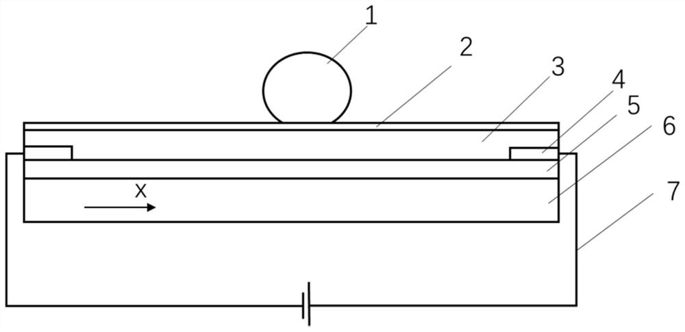
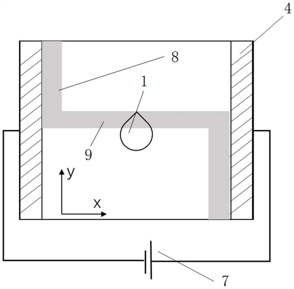
[0035] The present invention designs a method for manipulating droplets in multiple directions based on a single-plane light-controlled electro-wetting device. The basic principle of the single-plane light-controlled electro-wetting device is: the bias voltage applied to the electrodes 4 at both ends of the device is A transverse electric field is generated in the direction between the electrodes 4. When the light hits the surface of the photoconductive material, its conductivity increases, and the conductivity is smaller in places without light. By projecting dark stripes (no light) to a certain position on the chip, the stripes The resistivity of the covered area increases, and the dielectric layer 3 above it induces a large voltage drop. According to the Lippman-Young equation, the contact angle of the droplet 1 above the area decreases accordingly. If a dark fringe is applied over one side of droplet 1, the contact angle of droplet 1 changes asymmetrically, thereby driving ...

specific example

[0053] A specific example of the present invention is provided below, and its concrete realization process is:

[0054] 1. Put the purchased 4-inch single-sided polished silicon wafer into acetone solution for cleaning, rinse the surface of the silicon wafer with a dropper repeatedly until there is no debris or air bubbles left; put the silicon wafer into isopropanol solution for cleaning, wash away Residual acetone; rinse with deionized water repeatedly to remove the surface organic solvent; dry the silicon wafer surface with a nitrogen gun, and bake it on a hot plate at 100°C for 3-5 minutes until the silicon wafer is completely dried. The deposition of photoconductive thin film α-Si was carried out by PECVD. At 300℃ deposition temperature, the chamber pressure is 50-100Pa, SiH 4 The flow is 20sccm, H 2 The flow rate was 40sccm and the deposition power was 50W. Under this deposition power, the deposition rate of α-Si is about 5-10 nm / min, and the deposition is 100 min to ...


PUM

PropertyMeasurementUnit
Thicknessaaaaaaaaaa

Abstract

The invention relates to a method for controlling liquid drops in multiple directions on a single-plane light-operated electrowetting device. The method comprises the steps that bias voltage is applied to electrodes at the two ends of a single-plane light-operated electrowetting chip; dark fringes are projected on the single-plane light-operated electrowetting chip, and the electric field direction and the potential gradient on the chip are changed. The starting point and the ending point of the projection dark fringes are respectively located on the connecting line of the corresponding end parts of the two electrodes, the projection dark fringes penetrate through the liquid drops, and the normal direction of the projection dark fringes at the liquid drops is parallel to the target driving direction of the liquid drops. Compared with the prior art, by designing the driving pattern (projecting dark fringes) and changing the current direction and the potential gradient on the chip, driving control of the liquid drops in any direction is achieved, and flexible operation of the liquid drops is achieved.

Description

technical field [0001] The invention relates to the technical field of light-controlled electro-wetting, in particular to a method for multi-directional manipulation of droplets on a single-plane light-controlled electro-wetting device. Background technique [0002] In recent years, lab-on-a-chip technology has attracted the attention of many researchers due to its outstanding application prospects in biochemical reactions, medical detection and other fields. Among them, discrete flow technology represented by electrowetting on dielectric EWOD Digital microfluidic technology has been intensively studied due to its advantages of high throughput, small volume and flexibility. EWOD technology uses pixelated electrodes to perform a series of operations on droplets, such as generation, movement, and mixing, and can be applied in digital PCR, digital ELISA and other technologies. However, with the decreasing volume and increasing number of droplets operated by digital microfluidi...

Claims


Application Information

Patent Timeline
IPC IPC(8): B01L3/00
CPCB01L3/502792B01L2400/0427
Inventor 周嘉刘安刘恩清
Owner FUDAN UNIV
Why Eureka
Try Eureka