Pneumatic nailer with a safety device

a safety device and nailer technology, applied in the field of pneumatic nailers, can solve the problem of not being able to trigger a driving-in process, and achieve the effect of dampening the backward movement of the control valve member, avoiding unnecessary wear, and simple design solution

Active Publication Date: 2020-06-18
BEA GMBH
View PDF0 Cites 4 Cited by
  • Summary
  • Abstract
  • Description
  • Claims
  • Application Information

AI Technical Summary

Benefits of technology

[0027]In an embodiment, the damper is designed and coupled to the control valve member such that it does not dampen movement of the control valve member from the fully actuated position to the second switching point. This measure does not delay the damper's reaching of the second switching point, which also allows contact triggering in rapid succession.
[0028]In an embodiment, a mounting of the damper has a slot hole, so that a relative movement of two components connected via the damper over a section of a possible range of motion is not damped by the damper. Such a slot hole is a simple design solution to achieve undamped motion in a range of motion defined by the slot hole.
[0029]In an embodiment, a damping effect of the damper is limited to one of two possible directions of movement of the damper. For example, the damper can be designed in such a way that it is not acting if the control valve member is moved to a fully actuated position. It then only dampens the backward movement of the control valve member, which is important for the desired time-dependent behavior. In the other direction of motion, a simple displacement of the control valve member is possible, which enables a smooth movement sequence and avoids unnecessary wear.
[0030]In an embodiment, the damper comprises two elements movable relative to each other, the relative movement of which it dampens, one of the two elements being fixed and / or hinged to a part of the pneumatic nailer fixed to the housing, and the other of the two elements being fixed and / or hinged to the contact feeler, to the control valve member or to a force transmission device designed to transmit a force from the contact feeler to the control valve member. The three variants of this configuration concern different constructive solutions for the integration of the damper into the pneumatic nailer. In the first variant, the damper dampens the relative movement between the contact feeler and the housing of the pneumatic nailer. The relative movement of the contact feeler in relation to the housing is essentially linear and over a defined, relatively long distance. The desired damping of the relative movement is therefore particularly simple and robust. In the second variant, the damper dampens the relative movement between the control valve member and the housing of the pneumatic nailer. In contrast to the previous variant, the damper therefore acts directly on the control valve member. Such a direct damping of the movement of the control valve member can be particularly compact. In the third variant, the damper dampens the relative movement between a force transmission device and the housing of the pneumatic nailer. The force transmission device can, for example, be a rocker or a lever which is coupled to the contact feeler in order to act on the control valve member. This variant also allows effective integration of a damper in a compact design.

Problems solved by technology

If, on the other hand, the pneumatic nailer is in its locked state, it is not possible to trigger a driving-in process by actuating the release mechanism.

Method used


Image

  • Pneumatic nailer with a safety device
  • Pneumatic nailer with a safety device
  • Pneumatic nailer with a safety device

Examples


Embodiment Construction

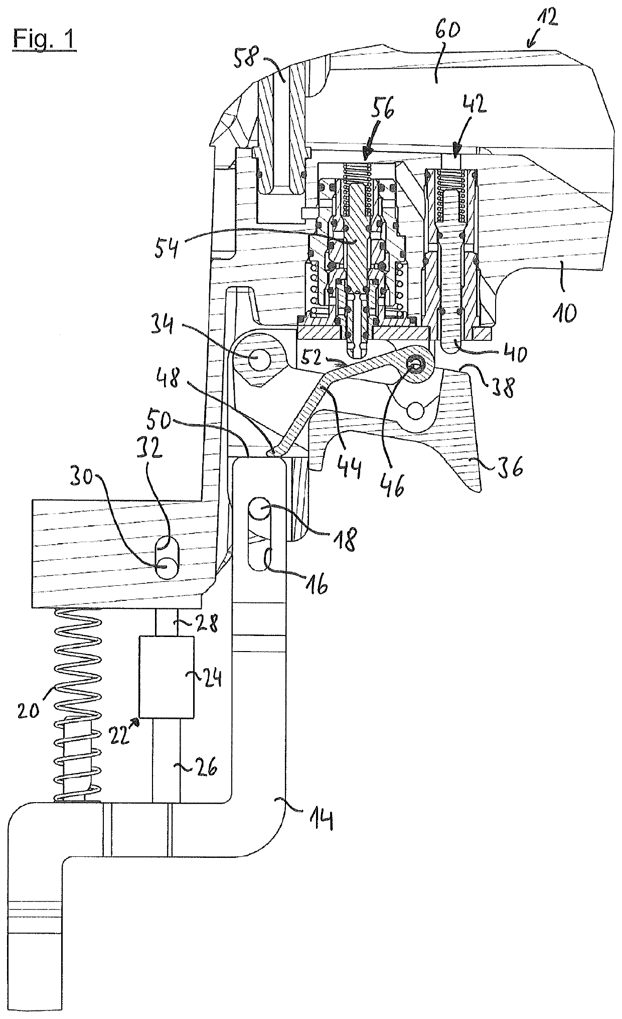
[0038]The pneumatic nailer, of which only a section is shown in FIG. 1, has a pneumatic connection and a working cylinder in which a working piston connected to a driving ram is slidably guided. The working cylinder is closed at the top by a main valve which is actuated by a pilot valve. As far as now and in the following the directions above and below are used, these refer to the normal working position of the pneumatic nailer, where the pneumatic nailer is placed on a workpiece with a horizontal surface. A magazine is used to hold a supply of fasteners, especially nails or staples, and ends at the front of a mouth tool into which individual fasteners are inserted. These are then driven into a workpiece by the driving ram when compressed air is applied to the working piston, controlled via the main valve and the pilot valve. These elements of the pneumatic nailer essentially correspond to the state of the art and can, for example, be designed as described in detail in EP 3 257 633 ...


PUM


Abstract

A pneumatic nailer is provided comprising a working piston which is connected to a driving plunger for driving in a fastening means and which is subject to compressed air when a driving-in process is triggered, The nailer also includes a triggering device for initiating a driving-in process, a safety device configured to switch the nailer from a trigger-ready state to a locked state a control valve to control the pressure inside of the control chamber which includes a control valve member which is moveable along an adjustment path and a damper coupled to the control valve member.

Description

CROSS REFERENCE TO RELATED DISCLOSURE[0001]This application is based upon and claims priority to, under relevant sections of 35 U.S.C. § 119, European Patent Application No. 18 212 051.9, filed Dec. 12, 2018, the entire contents of which are hereby incorporated by reference.TECHNICAL FIELD[0002]The disclosure relates to pneumatic nailers, and more particularly, to a pneumatic nailer having a new and useful safety device which is controlled by pressure in the control chamber of the pneumatic nailer.BACKGROUND[0003]Safety devices can prevent a pneumatic nailer from unintentionally carrying out a driving-in operation, as explained below, using the example of a pneumatic nailer with a contact feeler. When a pneumatic nailer is applied to a workpiece, the contact feeler is displaced against the force of a spring until a muzzle tool rests or almost rests against the workpiece. A driving-in process can only be triggered if the contact feeler is actuated in this way. Some pneumatic nailers ...

Claims


Application Information

Patent Timeline
Patent Type & Authority Applications(United States)
IPC IPC(8): B25C1/00B25C1/04
CPCB25C1/008B25C1/047B25C1/043B25C1/046
Inventor THEBERATH, MARTINBAUER, JOACHIM
Owner BEA GMBH
Why Eureka
Try Eureka