
Fuel cell system and its use

a fuel cell and system technology, applied in the field of fuel cell systems, can solve the problem achieve the effect of too low reaction ra

Inactive Publication Date: 2015-01-29
ELRINGKLINGER AG +1
View PDF3 Cites 1 Cited by
  • Summary
  • Abstract
  • Description
  • Claims
  • Application Information

AI Technical Summary

Benefits of technology

The invention is about a new catalytic material that increases the reaction rate of the shift reaction in a fuel cell system, even in the case of sulfur poisoning. The material is placed between the anode and an anode-side contact element, which ensures even current flow over the anode surface. The material can be made as a ceramic paste or a porous ceramic solid body, and it has the necessary properties to preserve and optimize its activity. The technical effect of this invention is to increase the efficiency and reliability of fuel cells, even in sulfur-contaminated environments.

Problems solved by technology

However, relatively precise investigations have shown that, to an overwhelming degree, this sulfur contamination relates only to the production of electrical energy from carbon monoxide (reaction 2), i.e., the carbon monoxide of the fuel gas passes through the fuel cell stack largely unused and is combusted in the residual gas burner, whilst the production of electrical energy from hydrogen (reaction 1) still takes place more or less unhindered.
However, without the catalytically active material provided according to the invention, the reaction rate is too low.

Method used


Image

  • Fuel cell system and its use
  • Fuel cell system and its use
  • Fuel cell system and its use

Examples


Embodiment Construction

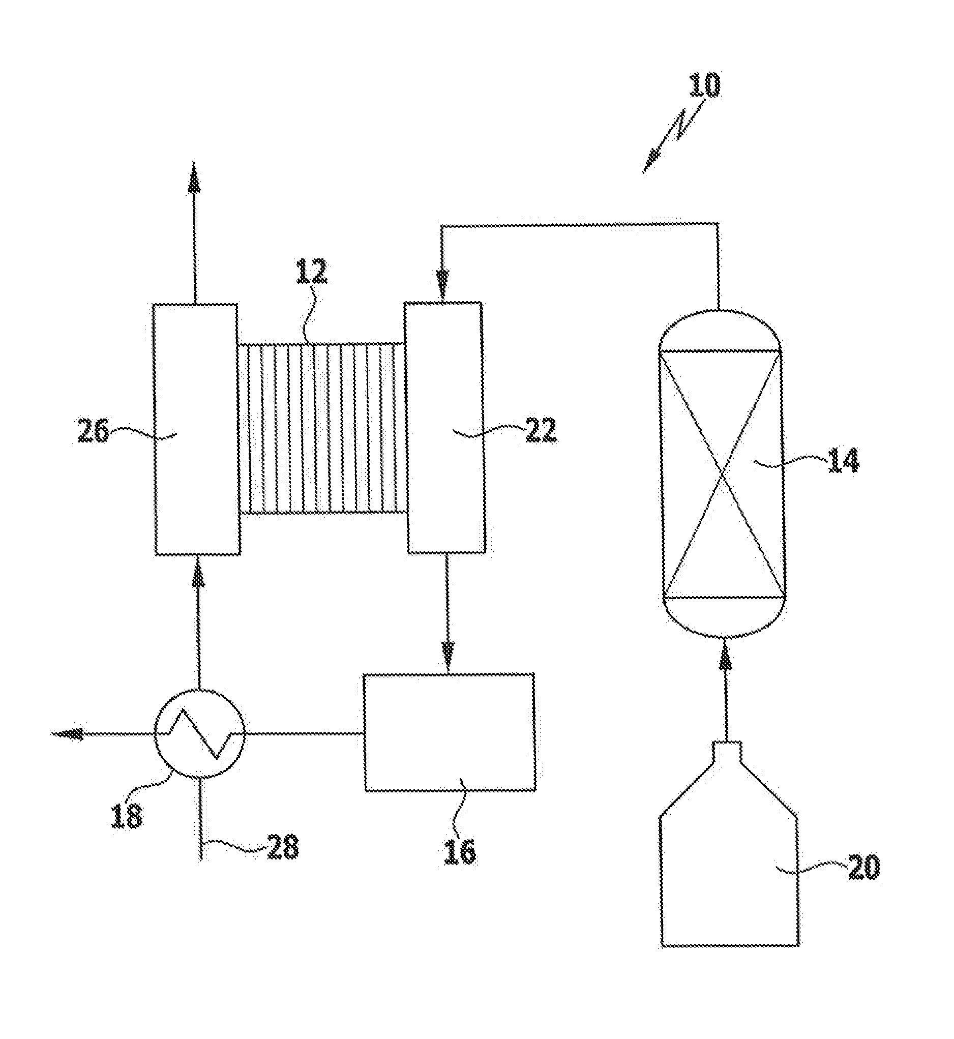
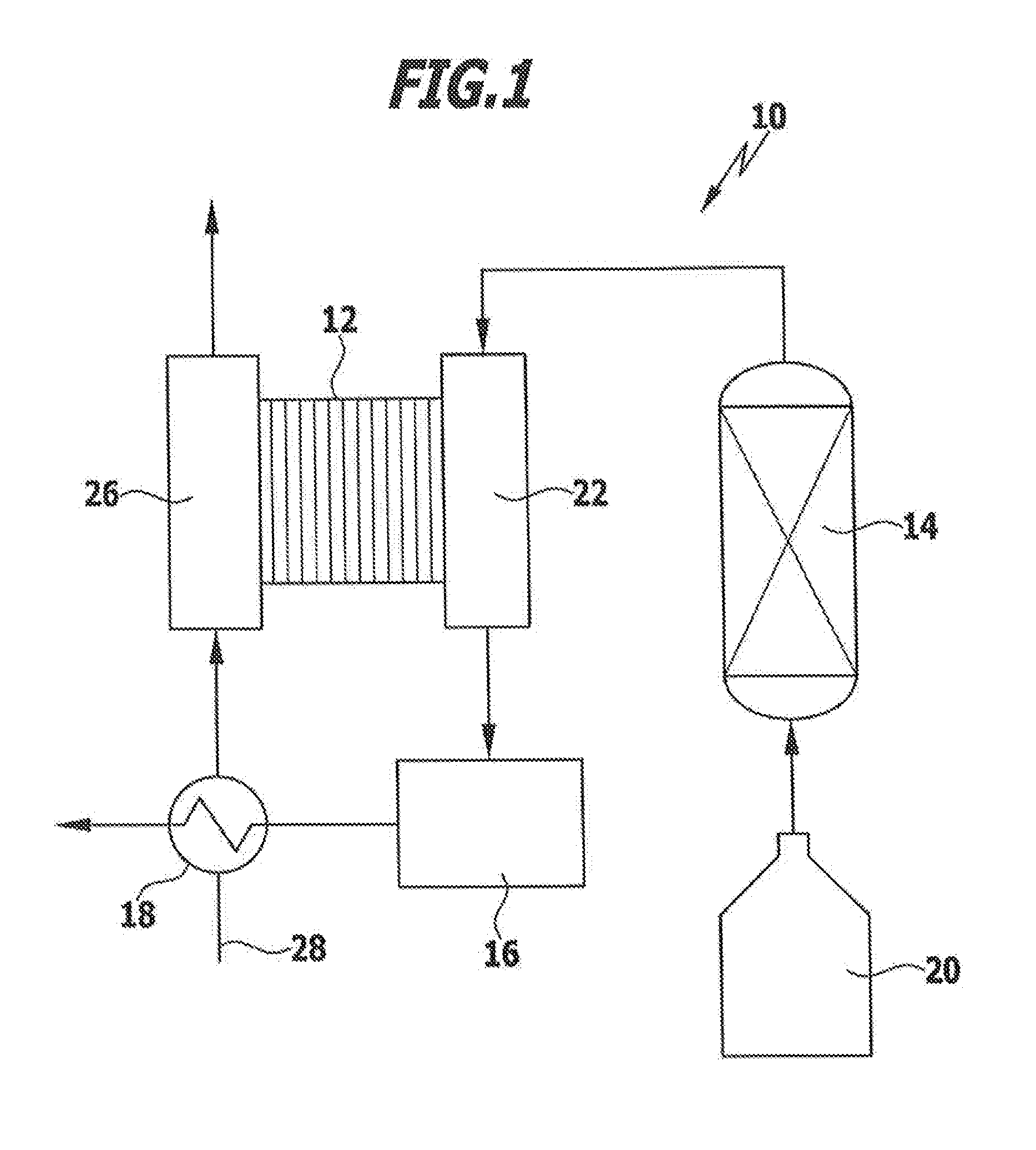
[0036]FIG. 1 shows schematically a fuel cell system according to one embodiment of the invention which is identified overall as 10. The fuel cell system 10 comprises a fuel cell stack 12 with a plurality of cathodes and anodes, a reformer 14, a residual gas burner 16 and a layered structure heat-exchanger 18.

[0037]During operation of the fuel cell system 10, fuel (e.g. diesel fuel) is fed from a fuel tank 20 to the reformer 14 (e.g. a steam reformer) where a fuel gas containing hydrogen and carbon monoxide is generated from the fuel. The fuel gas is fed to the anode side 22 of the fuel cell stack 12. By means of a catalytically active material which is arranged in the anode-side regions of the fuel cell stack 12 in each case upstream of the anode (not shown in FIG. 1), the complete or partial conversion of the carbon monoxide contained in the fuel gas with water to carbon dioxide and hydrogen is catalyzed. The hydrogen is electrochemically converted at the anodes of the fuel cell st...


PUM

PropertyMeasurementUnit
catalytic activityaaaaaaaaaa
electrical energyaaaaaaaaaa
temperatureaaaaaaaaaa

Abstract

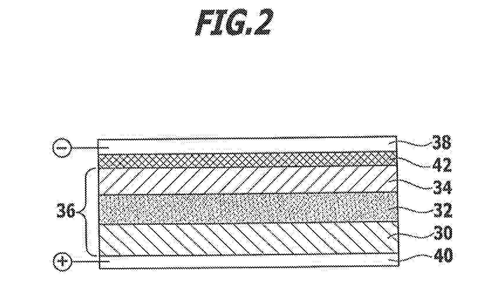
A fuel cell system is provided, including a fuel cell stack with a plurality of cathodes (30) and anodes (34), wherein an oxidizing gas containing oxygen is feedable to the stack on the cathode side and a fuel gas is feedable to the stack on the anode side, and a reformer for generating the fuel gas from a fuel. The fuel cell stack includes a catalytically active material (42) which is arranged in the anode-side regions such that the fuel gas flows through the material upstream of the anode (34), wherein the catalytically active material catalyzes the reaction of carbon monoxide and water to carbon dioxide and hydrogen.

Description

CROSS-REFERENCE TO RELATED APPLICATIONS[0001]The present application is a continuation of international application number PCT / EP2013 / 057686, filed on Apr. 12, 2013, which claims priority to German patent application number 10 2012 103 189.4, filed Apr. 13, 2012, the entire specification of both being incorporated herein by reference.FIELD OF INVENTION[0002]The present invention relates to a fuel cell system, comprising a fuel cell stack with a plurality of cathodes and anodes, wherein an oxidizing gas containing oxygen is feedable to the stack on the cathode side and a fuel gas is feedable to the stack on the anode side, and a reformer for generating the fuel gas from a fuel.[0003]The invention also relates to the use of a fuel cell system of this type for generating electrical energy in a motor vehicle which comprises an internal combustion engine powered by the fuel.BACKGROUND[0004]In order to be able to obtain electrical energy by means of a fuel cell from a fuel, as used, in pa...

Claims


Application Information

Patent Timeline
Patent Type & Authority Applications(United States)
IPC IPC(8): H01M8/06H01M8/10H01M8/24
CPCH01M8/0606H01M8/2465H01M2300/0074H01M8/0618H01M2008/1293H01M8/1016H01M8/0612H01M8/0668H01M4/8657H01M4/9033H01M4/9066H01M2004/8684H01M2250/20Y02E60/50Y02T90/40H01M8/2425
Inventor KIEFER, THOMASHOFFMANN, MARCOWEBER, ANDREKLUGE, CLAUS-PETER
Owner ELRINGKLINGER AG
Learn More