
Medical instrument

Active Publication Date: 2021-09-28
KARL STORZ GMBH & CO KG
View PDF14 Cites 0 Cited by
  • Summary
  • Abstract
  • Description
  • Claims
  • Application Information

AI Technical Summary

Benefits of technology

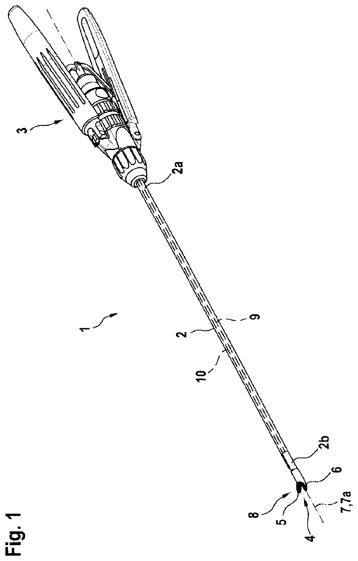
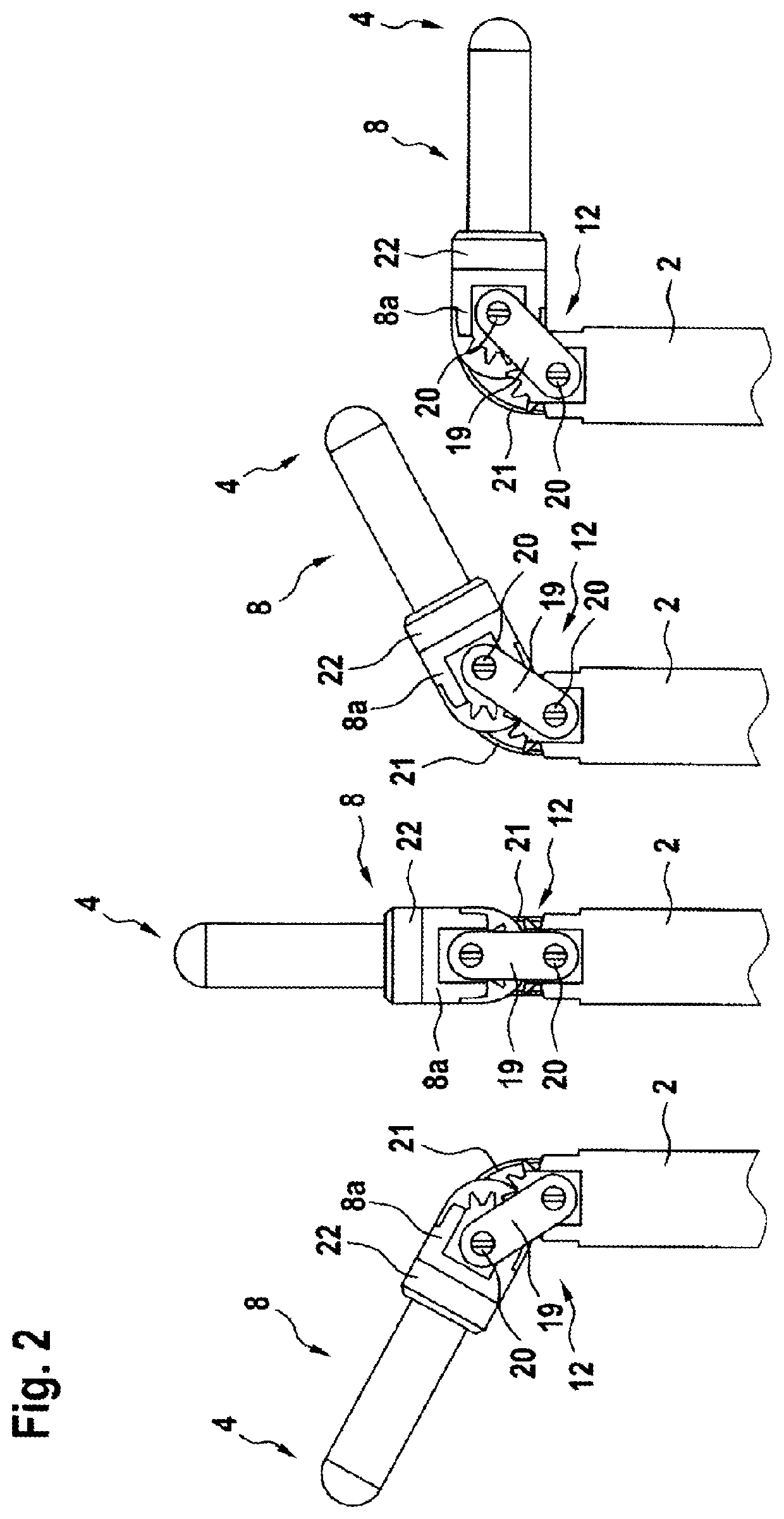
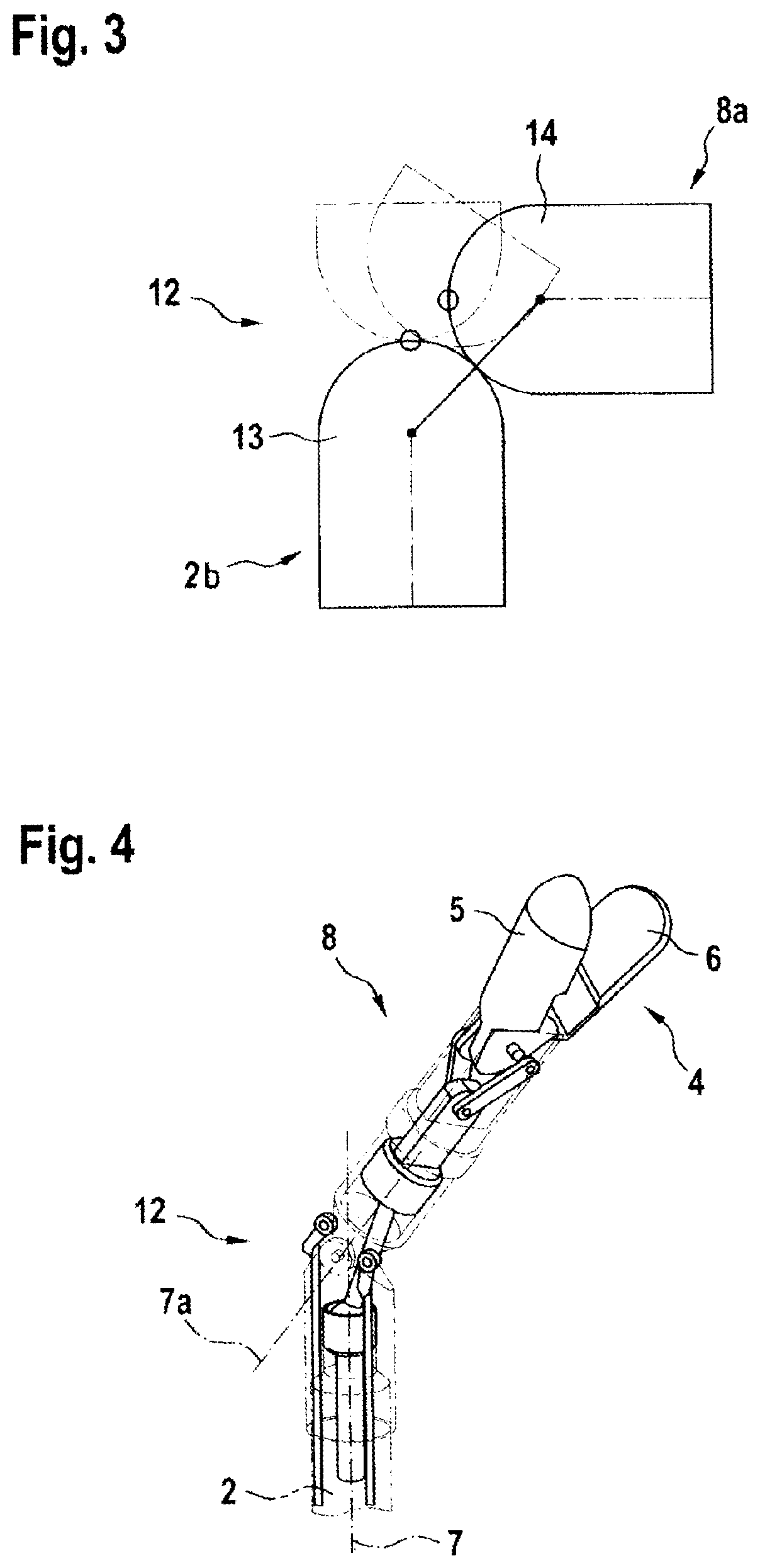
The invention is a medical instrument designed to have high transmission force, with many degrees of freedom and a small installation space. It includes gearwheel profiles that roll on each other, allowing for easy cleaning and wide deflection of the tool tip. The instrument is actuated through two pull / push elements fixed to the tool tip. The constant velocity drive joint allows for high forces while the joint is tilted about two axes. The invention also includes a wire that connects the ball head and ball socket of a homokinetic joint, improving the transmission of axial forces.

Problems solved by technology

Since instruments for use in endoscopic surgery need to be very small but at the same time need to grip very forcibly or permit cutting, the load on the joints and on the associated actuation mechanisms is very great.
These items of contamination of the control cables can be removed again only with very great difficulty during the cleaning of the instruments.
In addition, with the very small bending radii that are needed in the instrument heads, the control cables are not durable, as a result of which the period of use of these instruments is only a limited one.

Method used


Image

  • Medical instrument
  • Medical instrument
  • Medical instrument

Examples


first embodiment

[0050]In the first embodiment shown in FIGS. 6 and 7 for configuration of the drivetrain 11, the drivetrain 11 is composed of two identical joints which are connected in series one behind the other and are configured as CVD cardan joints 23.

[0051]Similarly to a known cardan joint, the constant velocity drive (CVD) joint 23 is based on a rotary cross 24 which however, in contrast to the known cardan joint, is not mounted in bifurcated recesses of the bearing axle but instead runs inside a holed ball 25. Since the CVD joint 23 is located inside the holed ball 25, the CVD joint 23 can withstand very high forces by virtue of the ball shape. The CVD joint 23 can transmit pushing and pulling forces while it is tilted about two axes.

[0052]Each CVD joint 23 in itself permits the transmission of pushing and pulling movements and rotation movements when the CVD joint 23 is deflected by an angle of up to 45°. Therefore, since at least two identical CVD joints 23 are connected in series, a defl...

second embodiment

[0053]According to the alternative second embodiment shown in FIGS. 8 and 9 for configuration of the drivetrain 11, the drivetrain 11 is composed of two identical joints which are connected in series one behind the other and are configured as homokinetic joints 26.

[0054]Homokinetic joints are characterized by the fact that they permit uniform transmission of angular velocity and torque from one shaft to a shaft arranged at an angle to the latter. The homokinetic joints 26 are composed of a ball socket 27 and a ball head 28, which seats in the ball socket 27. Both structural parts 27, 28 have up to six grooves 29 which are formed axially along the ball surfaces of ball socket 27 and ball head 28, wherein a groove 29 of the ball head 28 and a groove 29 of the ball socket 27 in each case form a groove pairing, in which a ball 30 is guided in a constrained manner. In addition, all balls 30 of each homokinetic joint 26 are guided in a common ball cage 31.

[0055]Each homokinetic joint 26 i...


PUM


Abstract

The application relates to a medical instrument with a hollow shaft, with a handle at the proximal end and a tool with two jaw parts at the distal end, of which at least one jaw part is pivotable, wherein a distal end region of the shaft is configured as a deflectable, rotatable tool tip, and wherein the jaw parts are adjustable between closed and open positions, wherein rotation of the tool tip and actuation of the jaw parts take place via actuation elements coupled at the proximal end to the handle. The distal end of the shaft and the proximal end of the tool tip are arc-shaped, and roll on each other for the deflection of the tool tip, and are conveyed from the shaft into the deflectable tool tip via at least two identical joints, which are connected in series and which can transmit rotation and translatory movements.

Description

TECHNICAL FIELD[0001]The invention relates to a medical instrument with a hollow shaft, at the proximal end of which a handle is arranged, and at the distal end of which a tool with two jaw parts is arranged, of which at least one jaw part is pivotable relative to the other jaw part, wherein a distal end region of the shaft that carries the tool is configured as a tool tip that can be deflected with respect to the longitudinal axis of the shaft, and the tool tip is rotatable about the longitudinal axis of the shaft respectively about the longitudinal axis of the tool tip, and wherein the at least one pivotable jaw part of the tool is adjustable between a closed position and an open position, wherein the rotation of the tool tip and the actuation of the jaw parts take place via actuation elements which are mounted in the shaft and which are coupled at the proximal end to the handle.BACKGROUND OF THE INVENTION[0002]Manually guided surgical instruments for minimally invasive operations...

Claims


Application Information

Patent Timeline
IPC IPC(8): A61B17/29A61B17/00
CPCA61B17/29A61B2017/00867A61B2017/2902A61B2017/2923A61B2017/2927A61B2017/2947A61B2017/0069A61B2017/292A61B2017/2929
Inventor HOFFMANN, MARTINFORSTER, JONASALBRECHT, SIMONBÖSE, GORDON
Owner KARL STORZ GMBH & CO KG
Learn More