
Power shift transmission

a transmission and power technology, applied in mechanical equipment, transportation and packaging, gearing, etc., can solve problems such as disadvantages, and achieve the effect of increasing the reliability of the change between transmission stages

Active Publication Date: 2020-06-18
RENK AG
View PDF0 Cites 0 Cited by
  • Summary
  • Abstract
  • Description
  • Claims
  • Application Information

AI Technical Summary

Benefits of technology

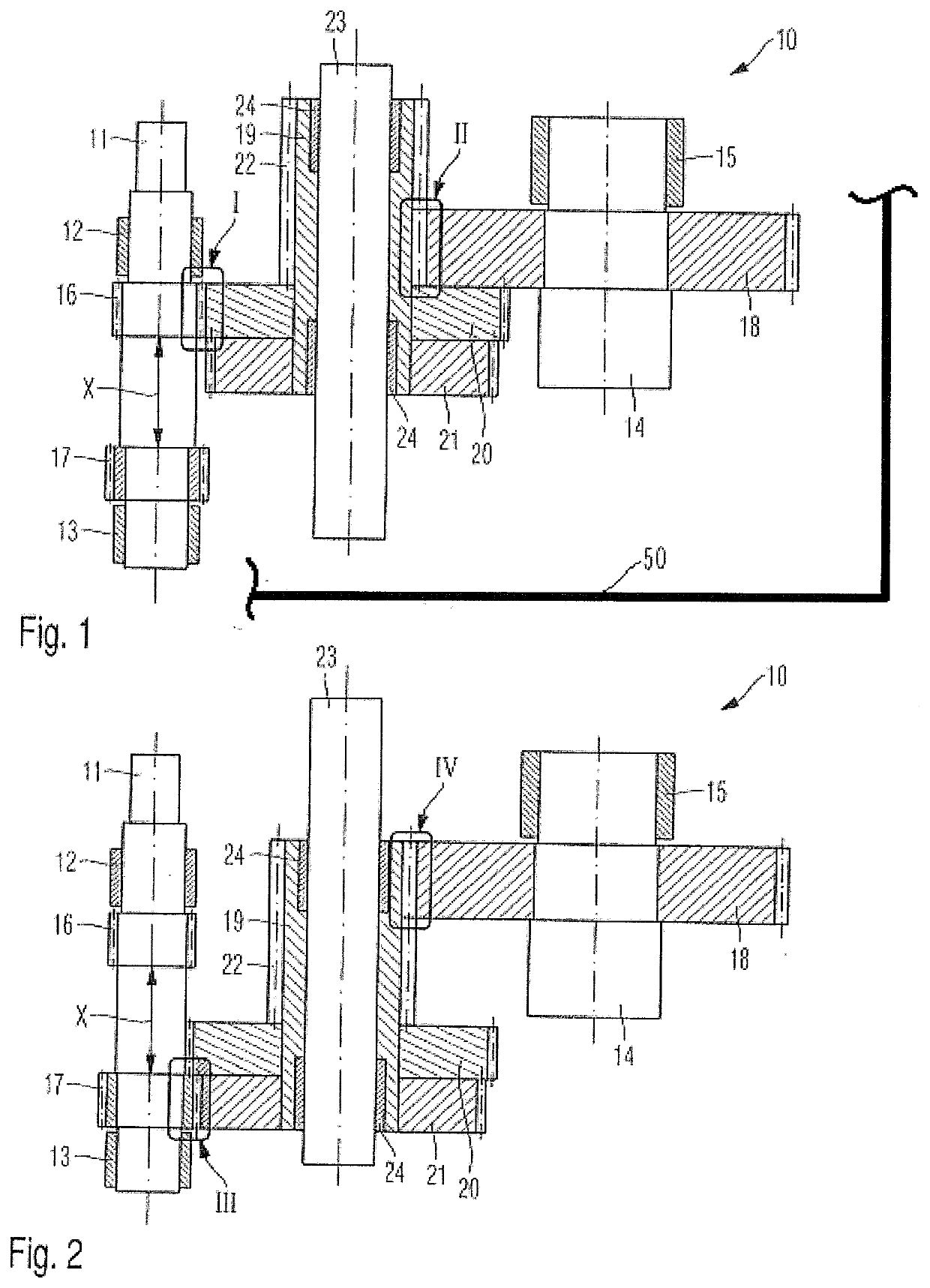
This patent describes a transmission system that allows for easy and reliable changing between different gear stages. The system includes a unit consisting of fourth, fifth, and sixth gear wheels, which can move both axially relative to the input and output shafts. The width of the sixth gear wheel is designed to ensure that it always engages with the third gear wheel, which increases reliability during gear changes.

Problems solved by technology

The axial moving of the input shaft also requires an axial moving of a drive flange coupled to the input shaft, which however is a disadvantage.

Method used


Image

  • Power shift transmission
  • Power shift transmission

Examples


Embodiment Construction

[0017]The invention relates to a power shift transmission which is embodied in particular as a heavy duty transmission such as an industrial transmission. Such a heavy duty transmission transmits a torque based on a slow-running shaft of at least 10 kNm, in particular of less than 50 kNm. The slow-running shaft can be both the input shaft and also the output shaft, typically the slow-running shaft of the heavy duty transmission is the output shaft. Such heavy duty transmissions are employed in different application cases such as for example as transmission for plants for the steel production and steel processing, in the plastics industry as transmission for extruders, as transmission for transport and conveyor systems for the open-cast industry, as transmission for cement mills, excavators, dredgers, or as transmission in plants for the power generation.

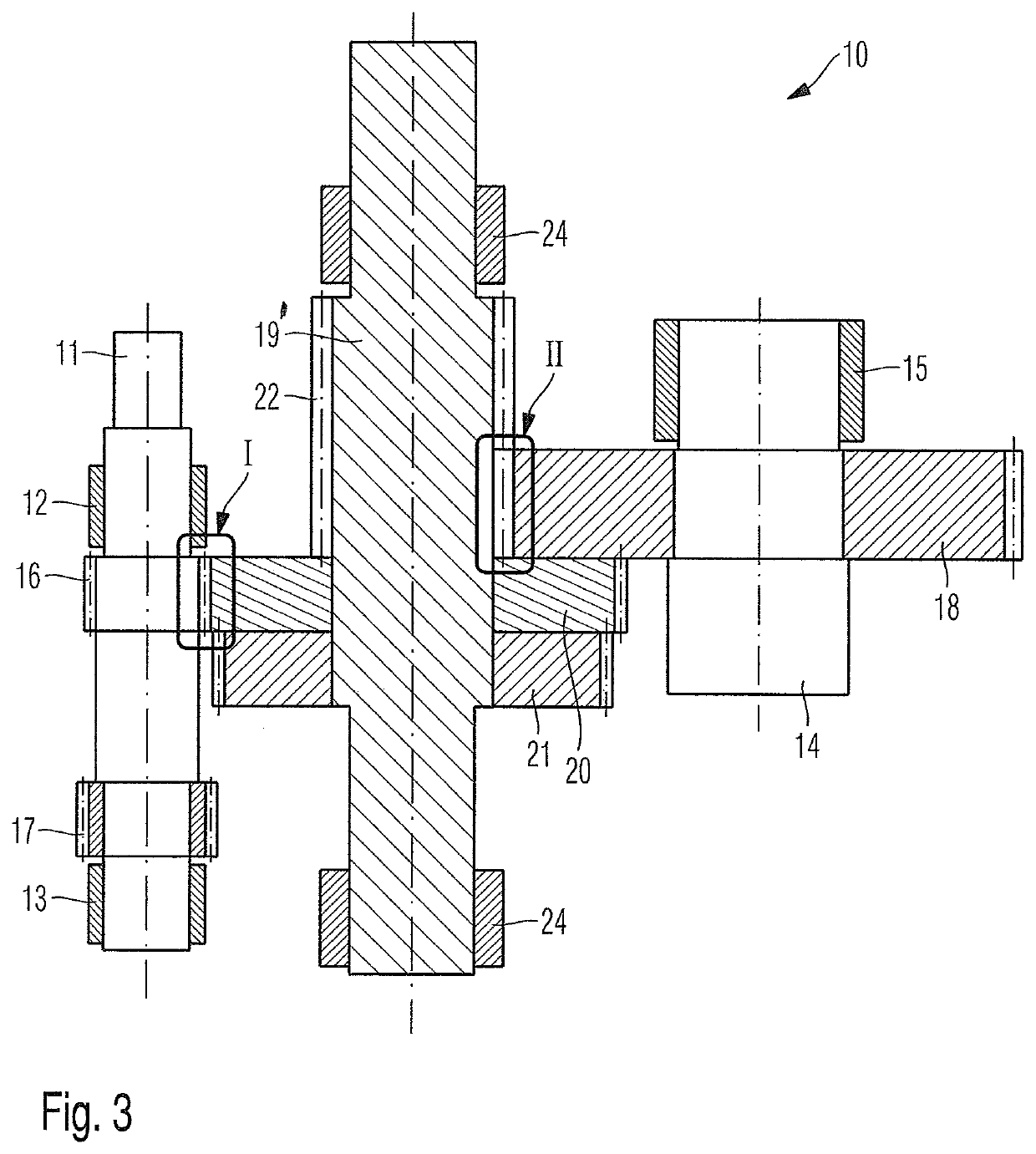
[0018]FIGS. 1 and 2 show a schematic representation of a first power shift transmission 10 according to one aspect of the invention...


PUM


Abstract

A power shift transmission, having an input and an output shaft, rotatably and axially immovably mounted and a rotatably mounted intermediate shaft. The input shaft carries first and second gear wheels. The output shaft carries a third gear wheel. The intermediate shaft carries a fourth, fifth, and sixth gear wheels, which are movable such that in a first shifting position the first gear wheel is in engagement with the fourth gear wheel and the sixth gear wheel is in engagement with the third gear wheel, but the second gear wheel and the fifth gear wheel are out of engagement, and in a second shifting position, the second gear wheel is in engagement with the fifth gear wheel and the sixth gear wheel is in engagement with the third gear wheel, but the first gear wheel and the fourth gear wheel are out of engagement.

Description

BACKGROUND OF THE INVENTION1. Field of the Invention[0001]The invention relates to a power shift transmission.2. Description of the Related Art[0002]From DE 10 2009 006 118 A1 a heavy duty power shift transmission formed as a power split transmission is known. The heavy duty power shift transmission comprises an input shaft, an output shaft, and two intermediate shafts. Axially spaced apart from one another, the input shaft carries two gear wheels, which are referred to as drive pinions, wherein through axial movement of the input shaft different transmission stages can be engaged or different transmission stages can be shifted into. The axial moving of the input shaft also requires an axial moving of a drive flange coupled to the input shaft, which however is a disadvantage.SUMMARY OF THE INVENTION[0003]There is a need for a new type of power shift transmission, with which a change between the transmission stages is possible without axially moving the input shaft and thus a drive f...

Claims


Application Information

Patent Timeline
Patent Type & Authority Applications(United States)
IPC IPC(8): F16H3/32
CPCF16H2200/0034F16H3/32
Inventor PINNEKAMP, BURKHARD
Owner RENK AG
Learn More