Grasping for tissue repair

a tissue and tissue technology, applied in the field of tissue repair, can solve the problems of difficult visualization of tissue capture or retention, difficult to distinguish between good and poor leaflet insertion and retention, and regurgitation,

Inactive Publication Date: 2020-07-02
ABBOTT CARDIOVASCULAR
View PDF0 Cites 9 Cited by
  • Summary
  • Abstract
  • Description
  • Claims
  • Application Information

AI Technical Summary

Benefits of technology

[0018]The device also includes an actuator for selectively moving the proximal elements between a first position in which the proximal elements are in a collapsed, low profile configuration for delivery of the device and a second position in which the proximal elements are in an expanded configuration for engaging a portion of the leaflets adjacent the mitral valve on the atrial side. Each distal element can also include a distal retaining element positioned along the distal engagement surface. Each distal retaining element is configured to cooperate with a corresponding proximal retaining element to capture a free edge of the mitral valve leaflet as the device is positioned relative to the mitral valve. Each retaining element can be configured to cooperate with a frictional element to allow a leading free edge of the leaflets to move in a first direction toward the body with little or no resistance or restriction and to resist or prevent movement of the free edge of the leaflets in an opposite direction away from the body.

Problems solved by technology

Regurgitation occurs when the valve leaflets do not close properly and allow leakage from the left ventricle into the left atrium.
Leaflet insertion may be assessed throughout the process of installing a fixation device 14, but it can be difficult to differentiate good and poor leaflet insertion and retention.
For example, when fixation device 14 is used in endovascular or minimally invasive procedures, visualization of the capturing or retention of tissue may be difficult.
Even if imaging methods make it possible to visualize when tissue is captured in the fixation device, they may not allow for a viewer to distinguish between securely and insecurely captured tissue.
This may result in the fixation device 14 being attached to only one of the leaflets LF, or separating from both leaflets LF, and no longer functioning as desired.
In addition to difficulties arising from the imaging or visualization of the device 14 as it is installed, difficulty in capturing or retaining tissue within fixation device 14 may also result from the nature of tissue desired to be captured or retained.

Method used


Image

  • Grasping for tissue repair
  • Grasping for tissue repair
  • Grasping for tissue repair

Examples


Embodiment Construction

[0032]I. INTRODUCTION[0033]A. Cardiac Physiology

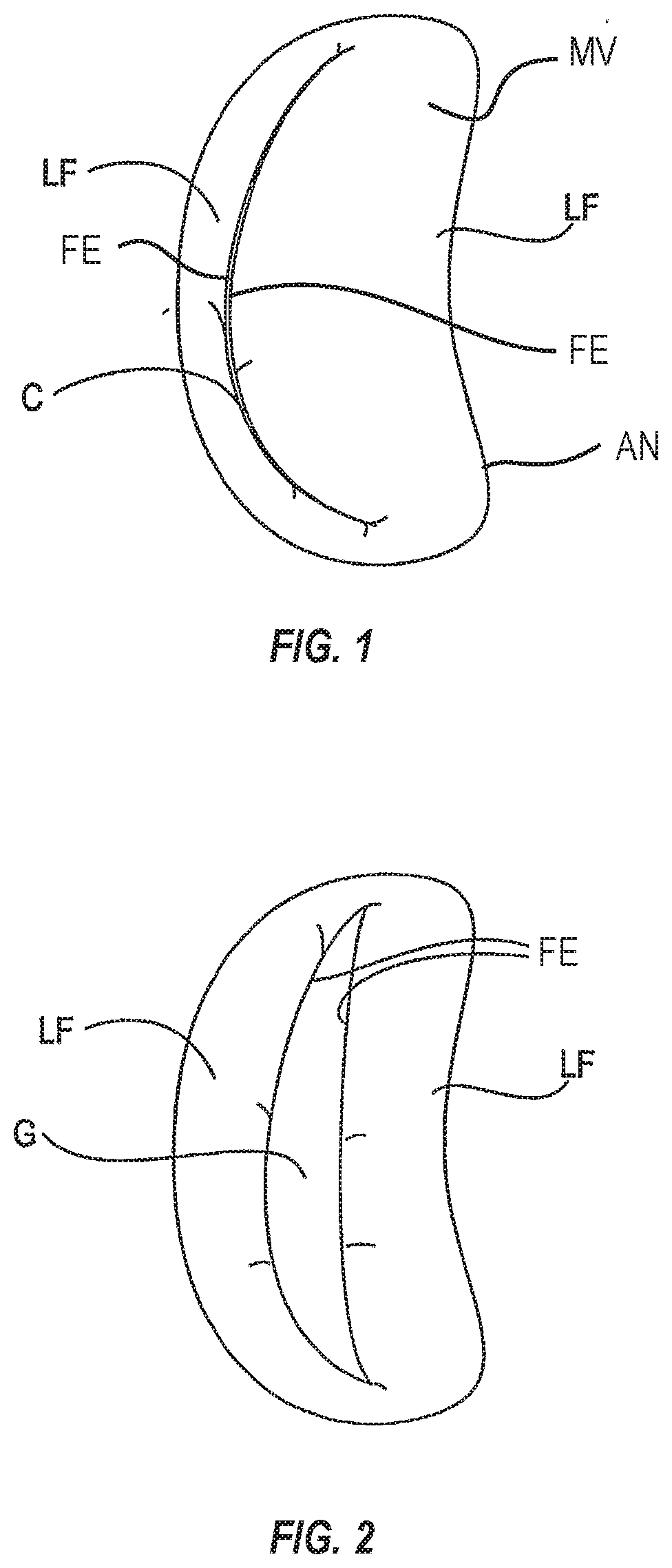
[0034]As shown in FIG. 1, the mitral valve (MV) comprises a pair of leaflets (LF) having free edges (FE) which, in patients with normal heart structure and function, meet evenly to close along a line of coaptation (C). The leaflets (LF) attach to the surrounding heart structure along an annular region called the annulus (AN). The free edges (FE) of the leaflets (LF) are secured to the lower portions of the left ventricle LV through chordae tendinae (or “chordae”).

[0035]As the left ventricle of a heart contracts (which is called “systole”), blood flow from the left ventricle to the left atrium through the mitral valve (MV) (called “mitral regurgitation”) is usually prevented by the mitral valve.

[0036]Regurgitation occurs when the valve leaflets do not close properly and allow leakage from the left ventricle into the left atrium. A number of heart structural defects can cause mitral regurgitation. FIG. 2 shows a mitral valve with a defec...


PUM


Abstract

The invention provides improved devices, systems, and methods for tissue approximation and repair at treatment sites. The invention provides devices, systems, and methods that may more successfully approximate and repair tissue by improving the capture of tissue into the devices. The invention may be a one-way mechanism that allows tissue to enter the mechanism but not easily exit, such as a leaf-spring, a protrusion, a pivoting arm and one or more frictional elements.

Description

CROSS REFERENCE TO RELATED APPLICATIONS[0001]The present application is a continuation application of U.S. patent application Ser. No. 16 / 748,450, filed on Jan. 21, 2020, which is a continuation application of U.S. patent application Ser. No. 16 / 241,647, filed on Jan. 7, 2019, which is a continuation application of U.S. patent application Ser. No. 14 / 577,852, filed on Dec. 19, 2014, issued as U.S. Pat. No. 10,188,392, the entire contents of which are incorporated herein by reference.BACKGROUND[0002]The present invention relates generally to medical methods, devices, and systems. In particular, the present invention relates to methods, devices, and systems for the endovascular, percutaneous, or minimally invasive surgical treatment of bodily tissues, such as tissue approximation or valve repair. More particularly, the present invention relates to repairing heart valves and venous valves, and devices and methods for removing or disabling mitral valve repair components through minimall...

Claims


Application Information

Patent Timeline
Patent Type & Authority Applications(United States)
IPC IPC(8): A61B17/08A61B17/128A61B17/122
CPCA61B2017/00783A61B17/08A61B17/122A61B2017/081A61B17/1285A61B2017/00243A61F2/246A61F2220/0091A61F2220/0016
Inventor WEI, MICHAEL F.
Owner ABBOTT CARDIOVASCULAR
Why Eureka
Try Eureka