Pneumatic tire

a technology of pneumatic tires and ribs, which is applied in the field of pneumatic tires, can solve the problems of insufficient heat dissipation effect of the block and insufficient heat dissipation effect of the ribs, and achieve the effects of improving and reducing the rigidity of the land portion

Active Publication Date: 2020-07-02
TOYO TIRE & RUBBER CO LTD
View PDF1 Cites 0 Cited by
  • Summary
  • Abstract
  • Description
  • Claims
  • Application Information

AI Technical Summary

Benefits of technology

The patent aims to improve the heat dissipation and maintain the rigidity of a land portion in a tire's tread area. This is done by providing a narrow groove with groove wall surfaces and a groove bottom surface in the land portion and an inclined surface on one of the groove wall surfaces facing each other in the tire's circumferential direction. The invention allows for improved heat dissipation while maintaining the land portion's rigidity.

Problems solved by technology

If the ratio of the projected area of the entire recesses to the block is less than 5%, the heat dissipation effect of the block tends to be insufficient.
If the ratio of the projected area of the entire recesses to the rib is less than 5%, the heat dissipation effect of the rib tends to be insufficient.

Method used


Image

  • Pneumatic tire
  • Pneumatic tire
  • Pneumatic tire

Examples


Embodiment Construction

[0028]Hereinafter, embodiments of the present invention will be described with reference to the attached drawings.

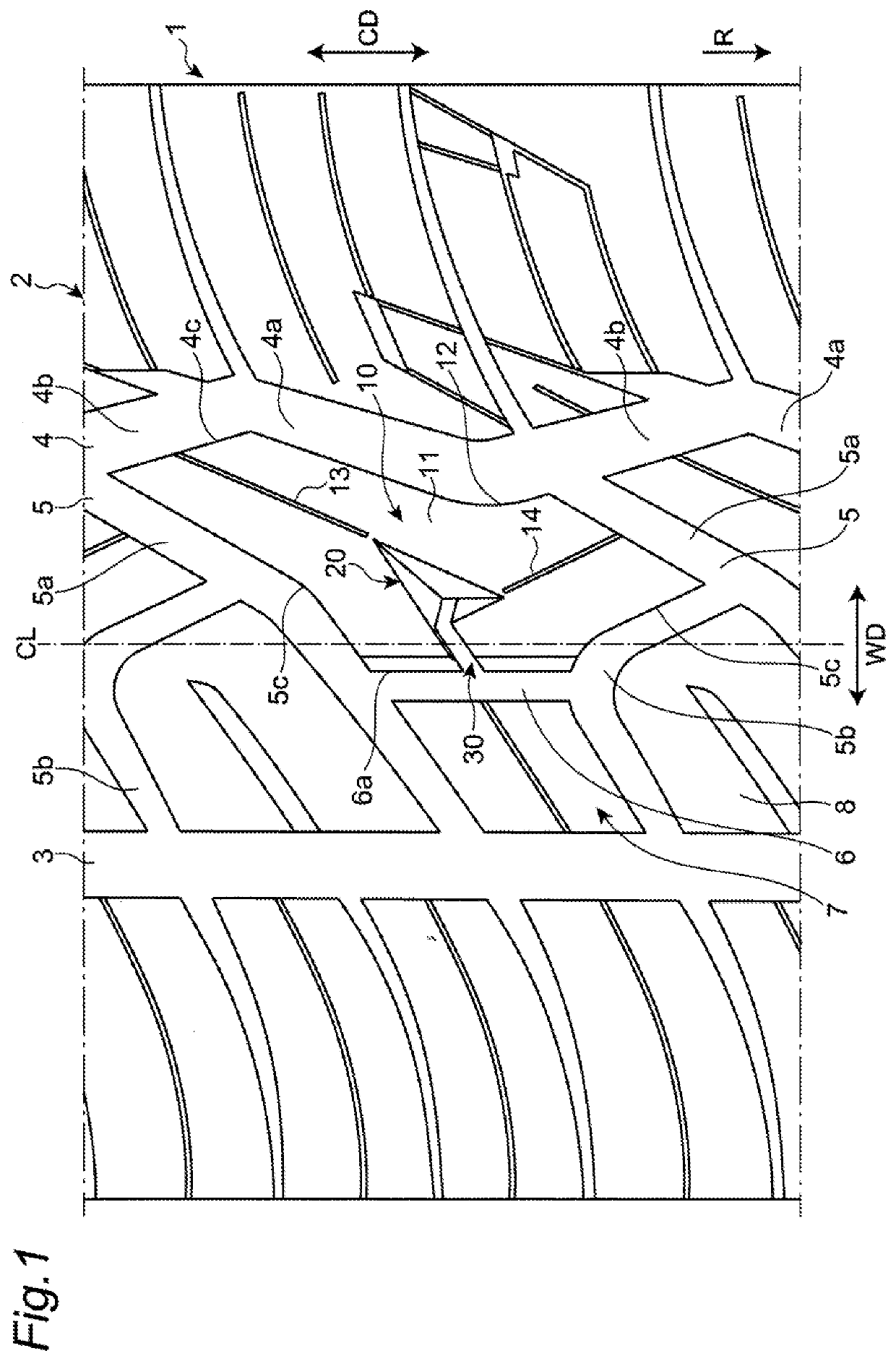
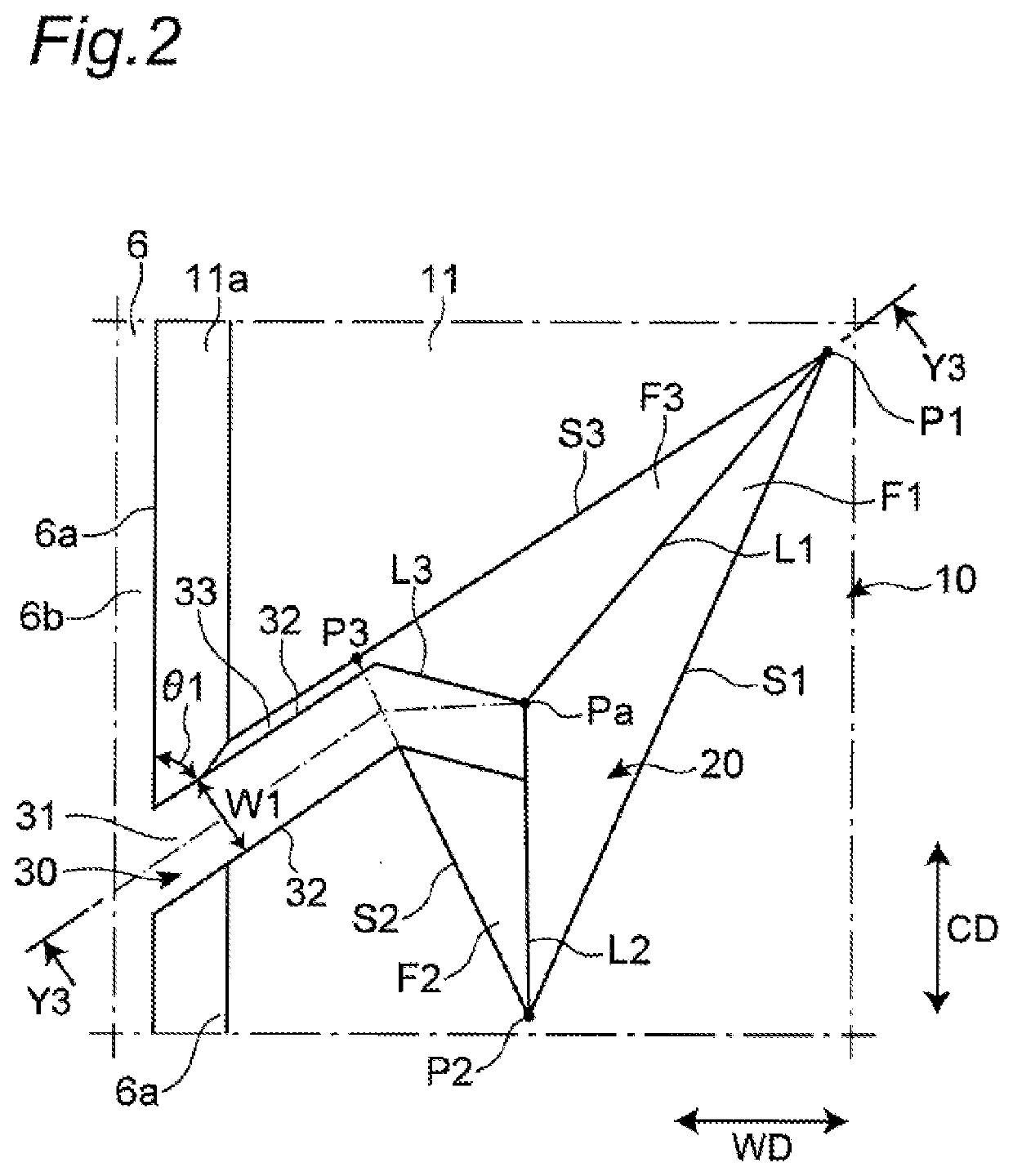
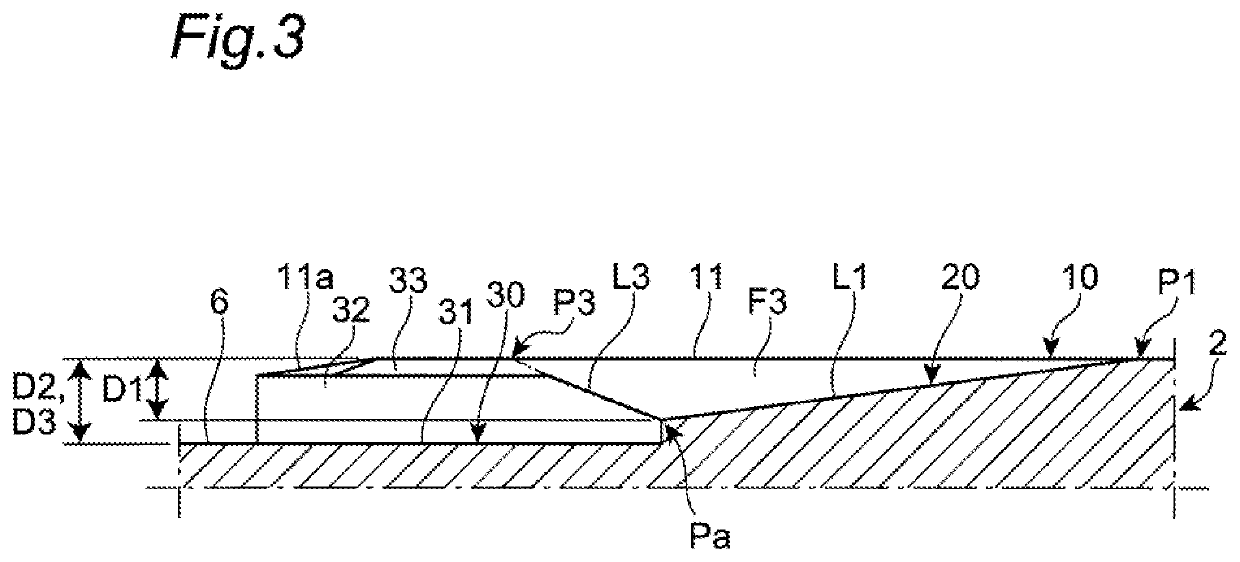
[0029]FIG. 1 is a development view illustrating a part of a tread portion of a pneumatic tire according to an embodiment of the present invention. Although not illustrated, the pneumatic tire 1 made of rubber according to an embodiment of the present invention is configured such that a carcass is spanned between a pair of bead cores, a belt is wound around the outer circumferential side of the middle part of the carcass for reinforcement, and the tire has a tread portion on the outer side of the belt in the tire radial direction.

[0030]As illustrated in FIG. 1, the pneumatic tire 1 has a tread portion 2. On the outer surface of the tread portion 2, a first longitudinal groove 3 and a second longitudinal groove 4 are formed, extending in a tire circumferential direction CD on the center side in a tire width direction WD and recessed inward in a tire radial direction. The f...


PUM


Abstract

A pneumatic tire includes a land portion provided in a tread portion and including a recess recessed inward in a tire radial direction. The recess includes three or more sides defining an opening that opens to a ground contact surface of the land portion and forming a polygon, and three or more side surface portions defined by the sides and line segments connecting respective vertexes of the sides and a bottom point provided on an inner side of the ground contact surface in the tire radial direction. The side surface portions are formed so as to approach the bottom point as the side surface portions extend inward in the tire radial direction from the ground contact surface.

Description

CROSS-REFERENCE TO RELATED APPLICATIONS[0001]This application claims priority of Japanese Patent Application No.: 2018-245804 filed on Dec. 27, 2018, the content of which is incorporated herein by reference.BACKGROUND OF THE INVENTIONTechnical Field[0002]The present invention relates to a pneumatic tire.Related Art[0003]In some known pneumatic tires, a recess recessed inward in the tire radial direction is formed in a land portion, such as a block and a rib, provided in a tread portion to improve the heat dissipation of the land portion and suppress a rise in the temperature of the land portion during the rolling of the tires.[0004]For example, Japanese Patent Application Laid-Open No. 2014-177139 discloses a pneumatic tire provided with a narrow groove including groove wall surfaces and a groove bottom surface and extending in a tire width direction in a land portion of a tread portion. One of the groove wall surfaces facing each other in the tire circumferential direction of the n...

Claims


Application Information

Patent Timeline
IPC IPC(8): B60C11/03
CPCB60C11/0304B60C11/0302B60C11/0323B60C11/0309B60C23/19B60C2011/036B60C2011/0372B60C2011/0341B60C2011/0346B60C11/032B60C2011/0381B60C11/1236
Inventor MATSUBARA, KEISUKE
Owner TOYO TIRE & RUBBER CO LTD
Why Eureka
Try Eureka