
Vibration Motor

Active Publication Date: 2020-07-02
AAC TECH PTE LTD
View PDF0 Cites 1 Cited by
  • Summary
  • Abstract
  • Description
  • Claims
  • Application Information

AI Technical Summary

Benefits of technology

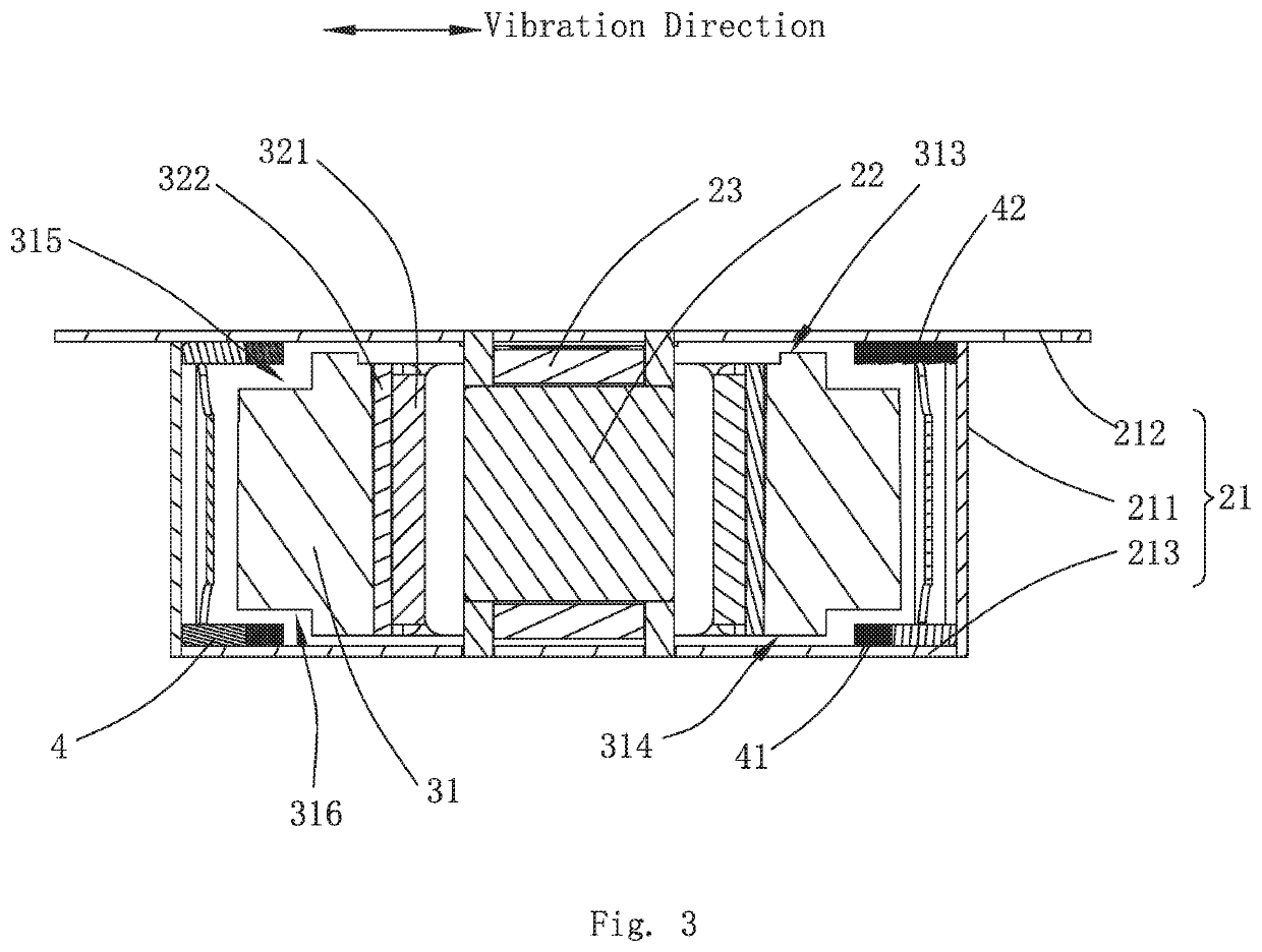
The present invention provides a vibration motor that solves the problem of losing function due to the collision between the vibrating component and the housing. The limit block is designed in a T shape, which increases the contact area between the limit block and the bottom plate, and reduces the risk of housing deformation and limit block disconnection. The vertical part of the T-shaped limit block prevents wrong match and can be easily identified when assembling.

Problems solved by technology

When working, the vibration motor needs to ensure enough driving force, however, over-high driving force causes the excessive amplitude of the vibrating component.
When the amplitude of the vibrating component is greater than the maximum vibrating space of the vibration motor, the vibrating component collides the housing, which makes the vibration motor lose function by impact and generate noises.

Method used


Image

  • Vibration Motor
  • Vibration Motor
  • Vibration Motor

Examples


Embodiment Construction

[0011]The present invention will hereinafter be described in detail with reference to an exemplary embodiment. To make the technical problems to be solved, technical solutions and beneficial effects of the present invention more apparent, the present invention is described in further detail together with the figure and the embodiment. It should be understood the specific embodiments described hereby is only to explain the invention, not intended to limit the invention.

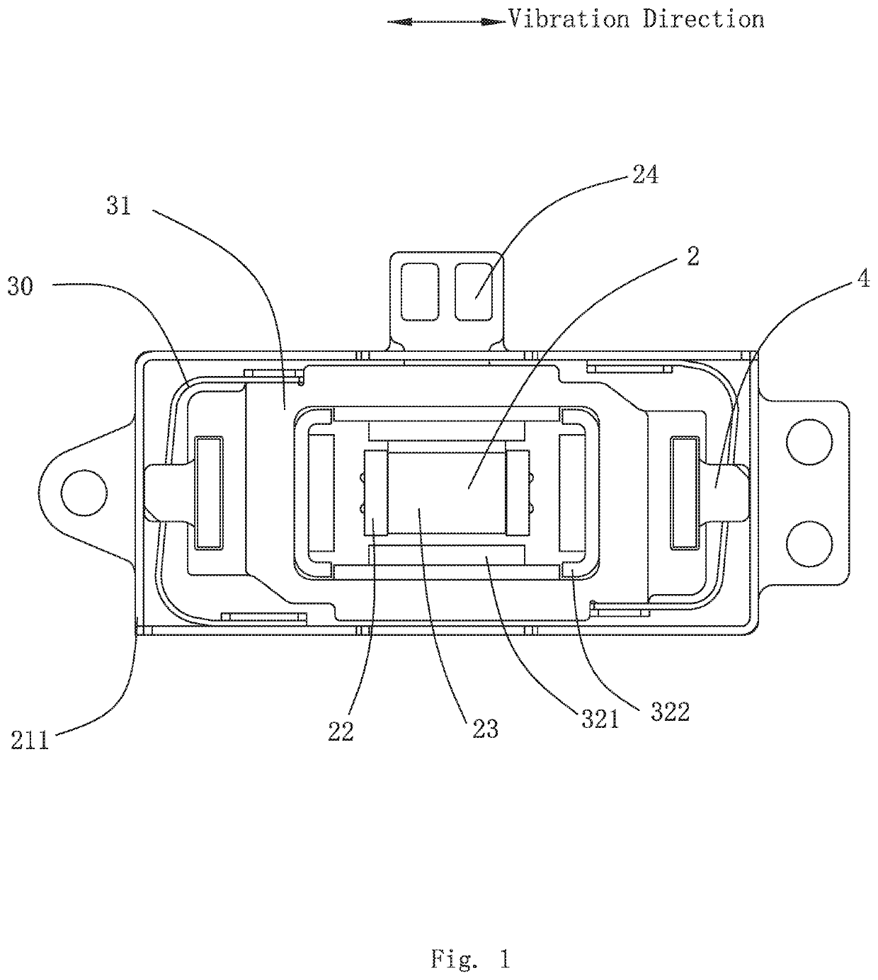
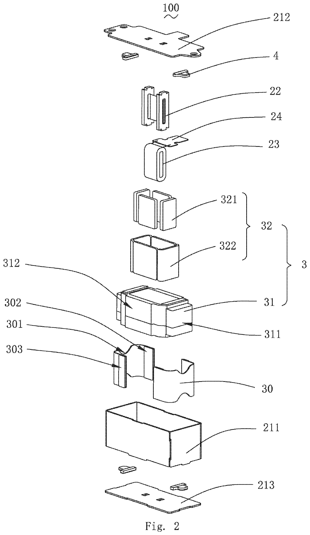
[0012]Please refer to FIGS. 1-2, the present invention provides a vibration motor 100. The vibration motor 100 comprises an elastic support part 30, a fixation component 2 and a vibrating component 3, wherein, the fixation component 2 comprises a housing 21 with an accommodation space, and the elastic support part 30 suspends and supports the vibrating component 3 in the accommodation space.

[0013]In the embodiment, the housing 21 comprises a frame 211 and an upper cover body 212 and a lower cover body 213 which are arr...


PUM


Abstract

An embodiment of the present invention provides a vibration motor. The vibration motor includes a vibrating component movable along a vibration direction; a fixation component including a housing with an s accommodation space; an elastic support part suspending the vibrating component in the accommodation space; and a number of limit blocks fixedly connected with the housing. Each of the limit blocks includes a horizontal part and a vertical part. The vertical part extends from the horizontal part towards the housing along the vibration direction. The vibration motor provided by the present invention can effectively solve the problem that the vibration motor loses function because of the collision between the vibrating component and the housing.

Description

FIELD OF THE PRESENT INVENTION[0001]The present invention relates to the technical field of electromagnetic motion parts, particularly to a vibration motor.DESCRIPTION OF RELATED ART[0002]The vibration motor is a component which uses the generation principle of electromagnetic force to convert electric energy into mechanical energy. The vibration motor is often arranged in the portable telephone and other electronic products to generate silent feedback signals.[0003]When working, the vibration motor needs to ensure enough driving force, however, over-high driving force causes the excessive amplitude of the vibrating component. When the amplitude of the vibrating component is greater than the maximum vibrating space of the vibration motor, the vibrating component collides the housing, which makes the vibration motor lose function by impact and generate noises.[0004]In addition, an over-big torque is applied to the limit block when the limit block is collided by the weight in the vibr...

Claims


Application Information

Patent Timeline
IPC IPC(8): H02K33/18
CPCH02K33/18B06B1/045H02K33/16H02K33/02
Inventor CUI, ZHIYONGTANG, YUN
Owner AAC TECH PTE LTD
Learn More