X-ray ct scanner, image generation method, and image generation program

Active Publication Date: 2020-07-09
FUJIFILM HEALTHCARE CORP
View PDF0 Cites 0 Cited by
  • Summary
  • Abstract
  • Description
  • Claims
  • Application Information

AI Technical Summary

Benefits of technology

The invention allows for a quick and sharp image of a structure with minimal streaking. This is possible because it reduces the time needed for calculations.

Problems solved by technology

However, if radiation dose of X-rays is insufficient in imaging a flat region such as shoulders, detected signals are likely to attenuate, resulting in increase of noise ratio, in a longitudinal direction where length of X-rays passing through a subject is long and a degree of X-ray attenuation is high.
It is well known that this may cause streak artifacts in an image (FIG. 14A).
Accordingly, this may cause a problem that blurring is likely to occur at the edge of the high-contrast structure within the subject in a reconstructed image.
There is a tradeoff between an effect of reducing streak artifacts and an effect of keeping sharpness on the edge of the structure, and thus when the former is enhanced, the latter becomes less effective.
In other words, increasing the degree of smoothing of the raw data to reduce strong streak artifacts may cause higher blurring at the edge of the structure within the subject in the reconstructed image (FIG. 14B).
Blurring at the edge of the structure within the subject is undesirable when the image is used for clinical diagnosis.

Method used


Image

  • X-ray ct scanner, image generation method, and image generation program
  • X-ray ct scanner, image generation method, and image generation program
  • X-ray ct scanner, image generation method, and image generation program

Examples


first embodiment

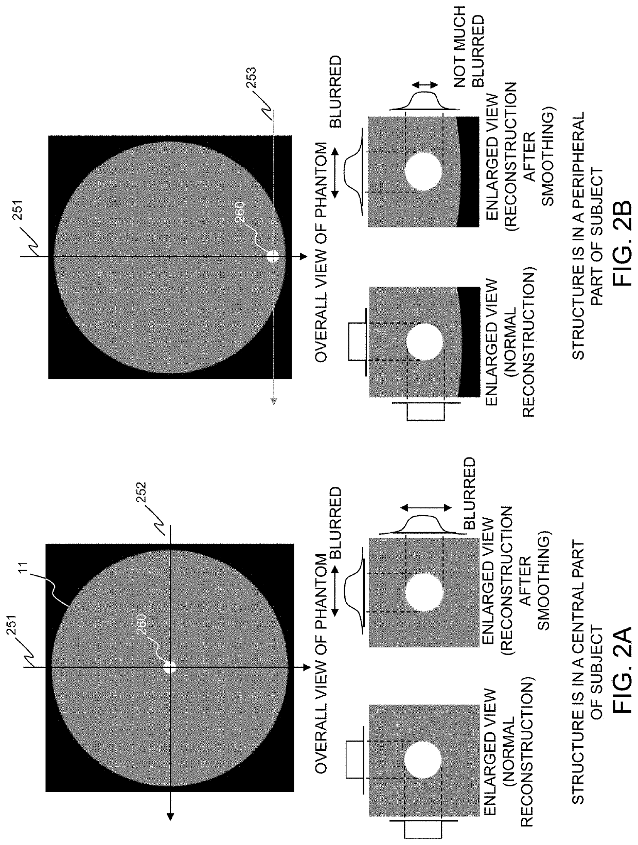
[0031]FIG. 1 is a block diagram showing an overview of the X-ray CT system of the present embodiment. FIGS. 2A and 2B illustrate a structure positioned in a central part of a subject and the structure positioned in a peripheral part thereof, and reconstructed images of the structure. FIG. 3 is a flowchart showing the process of the X-ray CT system.

[0032]As shown in FIG. 2A, X-rays passing through the structure 260 positioned in the central part of the subject 11 always pass through the center of the subject 11, when applied from any directions 251 and 252, allowing the X-ray to pass through the subject 11 for a long distance. On the other hand, as for the X-rays passing through the structure 260 positioned at the periphery part of the subject 11, there is a direction 253 that allows the X-ray to pass through the subject 11 for a short distance. The detected signals of the X-ray passing through the structure 260 positioned in the central part of the subject 11 are likely to include m...

second embodiment

[0047]With reference to FIG. 4 and other related figures, there will be described the X-ray CT system of the second embodiment. The elements already described in the first embodiment are labeled with the same reference numerals, and redundant descriptions will not be provided.

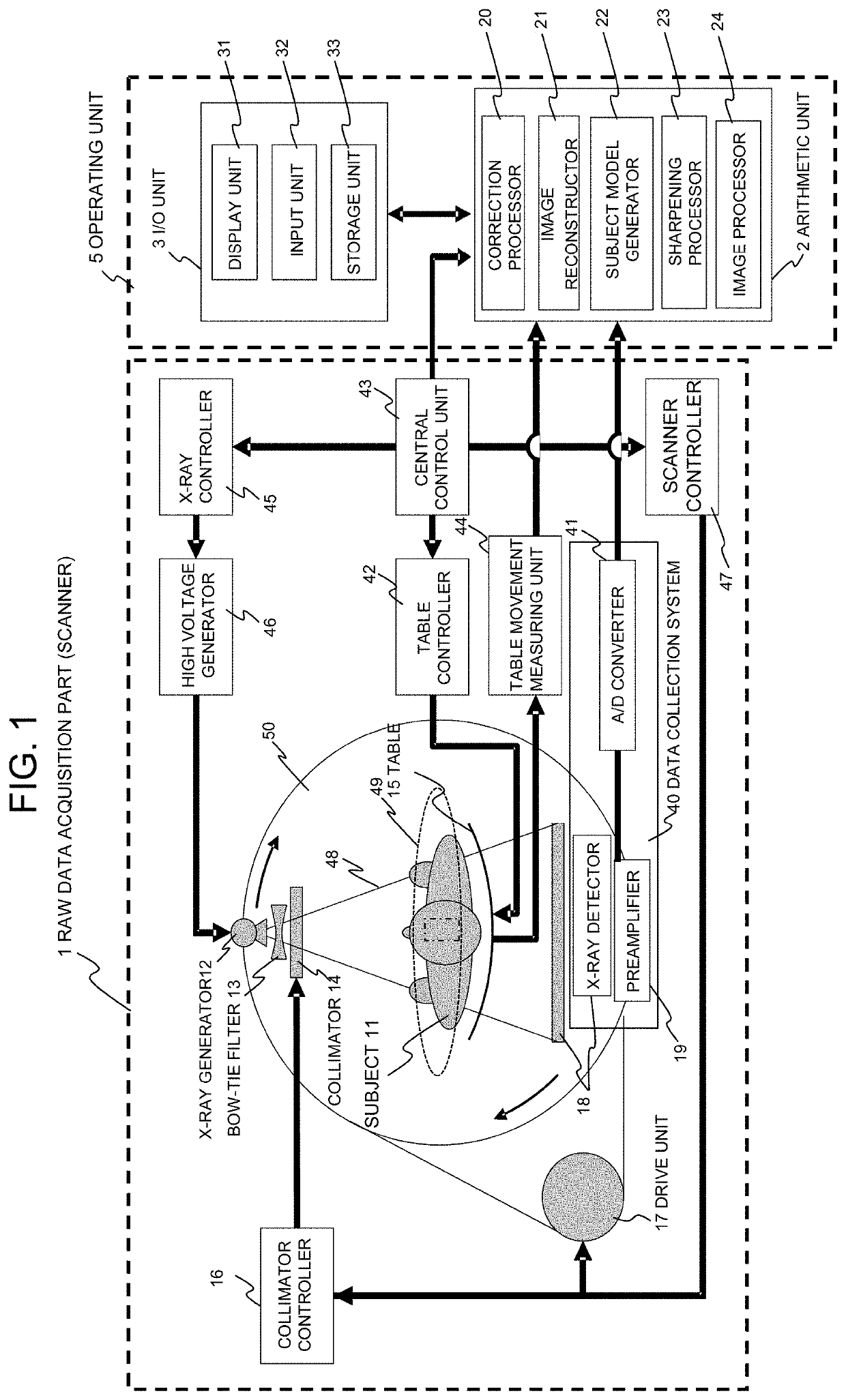
[0048]FIG. 4 is a perspective view showing an outward appearance of the X-ray CT system according to the first embodiment. As illustrated in FIGS. 1 and 4, the X-ray CT system of the first embodiment is provided with a raw data acquisition part (hereinafter referred to as a scanner) 1, a table 15 for moving a subject placed thereon, an I / O unit 3, and arithmetic unit 2. The I / O unit 3 includes an input unit 32 comprising a mouse and a keyboard configured to input parameters for measurement and reconstruction, such as table moving speed information and a position for reconstruction, and a display unit 31 configured to display a reconstructed image and other information.

[0049]As illustrated in FIG. 1, the scanner...

third embodiment

[0092]There will now be described the X-ray CT system of the third embodiment.

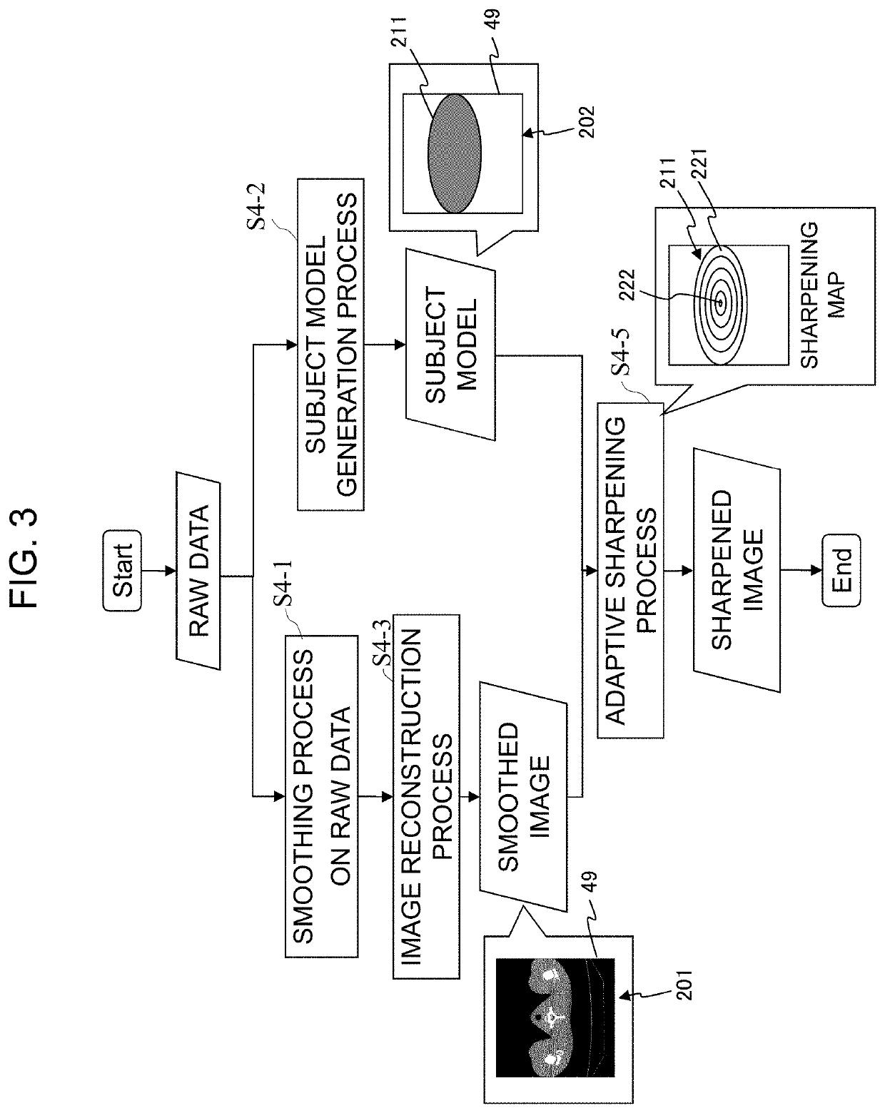
[0093]In the second embodiment, the shape of the subject 11 is approximated by the ellipse 211, so as to create the subject model 202, but in approximating the actual subject 11, there may be found some disagreement in the shape of the ellipse 211, in approximating the actual subject 11. Since X-ray detection strength changes abruptly around the body surface or bones of the subject 11, the signal reduction level varies significantly in response to such changes. Therefore, around the body surface or bones of the subject 11, the disagreement in shapes between the ellipse 211 and the subject 11 may have significant impact on the image quality. For example, around the body surface of the subject 11, adjacent detector elements may detect the X-rays passing through the subject 11, and the X-rays passing through the air, respectively. Therefore, when the ellipse 211 being provided is larger than the region of the...


PUM


Abstract

An image is generated where an edge of a structure in a subject is sharpened with reducing streak artifacts, within a short amount of time. X-rays at multiple angles are applied to the subject placed in imaging space, and a distribution of X-rays strength passing through the subject is detected to obtain raw data associated with multiple views. After smoothing the raw data associated with multiple views, image reconstruction is performed to generate a smoothed image of a predetermined region to be imaged in the imaging space. In the smoothed image, more intense sharpening process is applied to pixels in a region of a central part of the subject, than the pixels in a region of a peripheral part of the subject.

Description

TECHNICAL FIELD[0001]The present invention relates to an X-ray CT system, and more particularly, to an X-ray CT system that achieves both reduction of streak artifacts and edge sharpening of a structure in a generated CT image.BACKGROUND ART[0002]X-ray CT systems are widely used as medical-use tomographic imaging devices to create an image of a human body non-invasively. To address growing concern about radiation exposure in recent years, reduction of exposure dose is being demanded in CT scanning. However, if radiation dose of X-rays is insufficient in imaging a flat region such as shoulders, detected signals are likely to attenuate, resulting in increase of noise ratio, in a longitudinal direction where length of X-rays passing through a subject is long and a degree of X-ray attenuation is high. It is well known that this may cause streak artifacts in an image (FIG. 14A).[0003]Given these circumstances, image processing methods have been extensively studied for improving an image ...

Claims


Application Information

Patent Timeline
IPC IPC(8): G06T7/00G06T5/00G06T17/10
CPCG06T7/0012G06T5/002G06T5/003G06T2207/10081G06T17/10A61B6/03G06T11/006G06T5/70G06T5/73
Inventor TAKAHASHI, HISASHIGOTOU, TAIGAHIROKAWA, KOICHI
Owner FUJIFILM HEALTHCARE CORP
Why Eureka
Try Eureka