Method for optimal path selection for data traffic undergoing high processing or queuing delay

a data traffic and optimal path technology, applied in the field of optimal path selection, can solve the problems of packet loss, heavy processing performed by such appliances, and jitter, and achieve the effect of reducing or eliminating packet loss, reducing or eliminating latency, jitter and packet loss in the network

Active Publication Date: 2020-07-09
CITRIX SYST INC
View PDF0 Cites 34 Cited by
  • Summary
  • Abstract
  • Description
  • Claims
  • Application Information

AI Technical Summary

Benefits of technology

[0012]In either scenario, once the communication path is selected, the server-side intermediary device may initiate transmission of the packets to the client-side intermediary device via the communication path to be buffered at the client-side intermediary device until further instruction. The client-side intermediary device may have a limit to the number of packets that may be buffered, and may transmit a feedback signal to the server-side intermediary device if the number is exceeded. As the heavy processing is being performed (e.g., security inspection), the server-side intermediary

Problems solved by technology

As these packets travel toward the destined network device from one intermediary device to another intermediary device through one of the communication paths of the network, the packets may experience delay.
While inspecting packets for signs of vulnerability may provide additional security, the heavy processing performed by such appliances may incur additional delay.
The delay in the delivery of packet through the communication paths of the network may lead to a whole host of deleterious effects on communi

Method used


Image

  • Method for optimal path selection for data traffic undergoing high processing or queuing delay
  • Method for optimal path selection for data traffic undergoing high processing or queuing delay
  • Method for optimal path selection for data traffic undergoing high processing or queuing delay

Examples


Embodiment Construction

[0031]For purposes of reading the description of the various embodiments below, the following descriptions of the sections of the specification and their respective contents may be helpful:

[0032]Section A describes a network environment and computing environment which may be useful for practicing embodiments described herein;

[0033]Section B describes embodiments of systems and methods for delivering a computing environment to a remote user;

[0034]Section C describes embodiments of systems and methods for virtualizing an application delivery controller;

[0035]Section D describes embodiments of systems and methods for providing a clustered appliance architecture environment; and

[0036]Section E describes embodiments of systems and methods for path selection proportional to a penalty delay in processing packets.

A. Network and Computing Environment

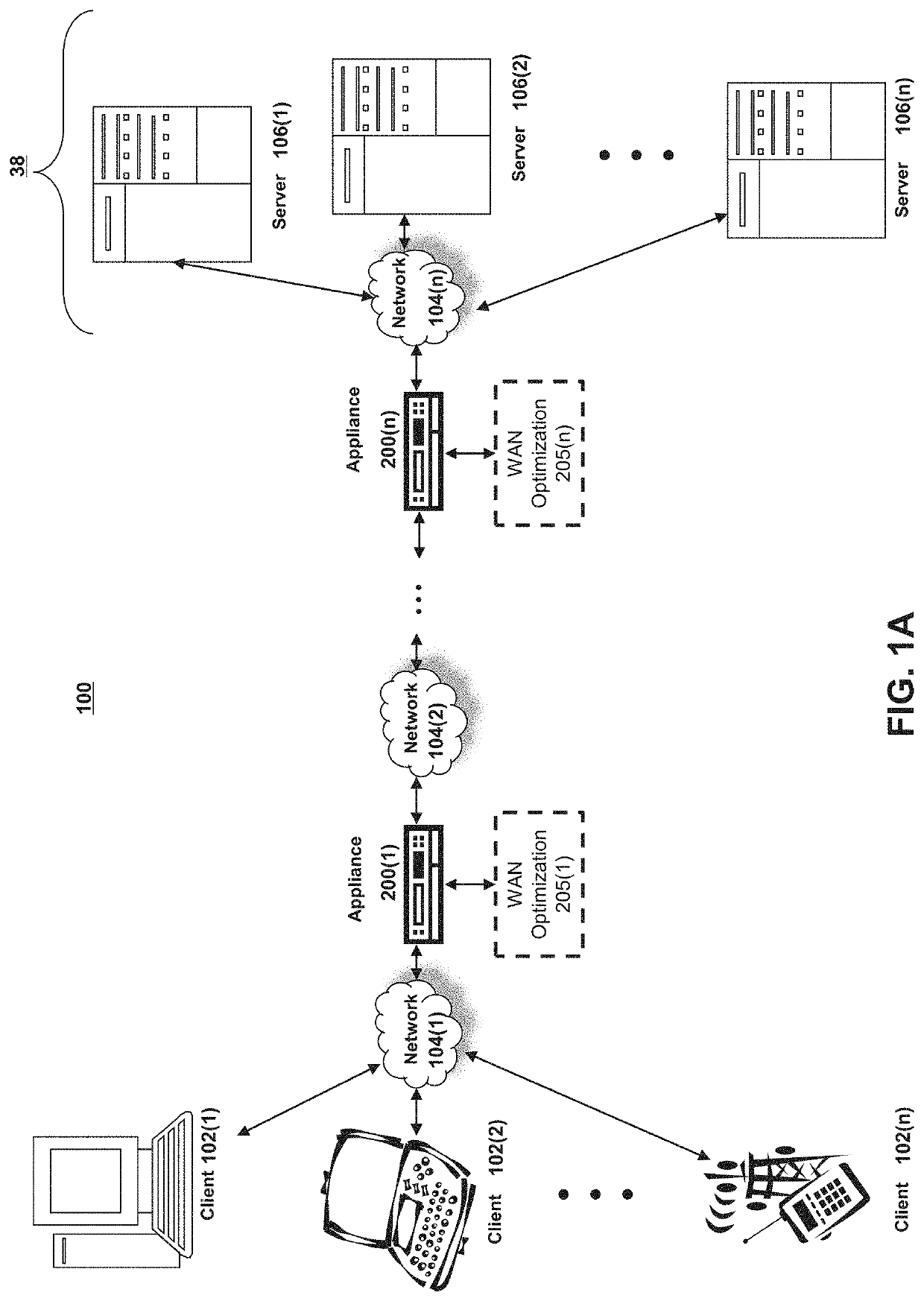
[0037]Referring to FIG. 1A, an illustrative network environment 100 is depicted. Network environment 100 may include one or more clients 102(1)-...


PUM


Abstract

Described embodiments provide systems and methods for path selection proportional to a penalty delay in processing packets. A server-side intermediary may identify a delay penalty for processing packets of a server destined for a client. The server-side intermediary may be in communication via links of different latencies with a client-side intermediary. The server-side intermediary may select a second link with a latency that deviates from the lowest latency of a first link by the delay penalty. The server-side intermediary may transmit, to the client-side intermediary, duplicates of the packets via the selected second link with information indicating to hold the duplicates at the client-side intermediary. The server-side intermediary may receive an indication to drop or send the duplicates to the client. The server-side intermediary may transmit the indication to the client-side intermediary to drop or send the duplicates according to the indication.

Description

FIELD OF THE DISCLOSURE[0001]The present application generally relates to routing of packets. In particular, the present application relates to systems and methods for path selection proportional to a penalty delay in processing packets.BACKGROUND[0002]A network device may send packets to another network device via a communication path for accessing resources for an application. The packets may undergo delay in arriving at the destined network device. The delay may be due to various factors, such as processing and buffering of multiple packets at each network device along the communication path and traversal over the communication path itself.BRIEF SUMMARY[0003]This summary is provided to introduce a selection of concepts in a simplified form that are further described below in the Detailed Description. This summary is not intended to identify key features or essential features, nor is it intended to limit the scope of the claims included herewith.[0004]Network devices may exchange ...

Claims


Application Information

Patent Timeline
IPC IPC(8): H04L12/727H04L12/823H04L12/861H04L29/06H04L45/121H04L47/32
CPCH04L47/32H04L49/90H04L12/28H04L63/20H04L45/121H04L43/0864H04L69/14H04L41/046H04L43/16H04L43/0876H04L45/24H04L67/288H04L67/567H04L67/61H04L67/63H04L41/0894H04L41/40H04L43/20H04L49/9023
Inventor DHANABALAN, PRAVEEN RAJA
Owner CITRIX SYST INC
Why Eureka
Try Eureka