
Endoscope

a technology of endoscope and proximal end side, which is applied in the field of endoscope, can solve the problems of impaired operability of the operating part, enlarged or complicated operating parts, and complicated attachment and detachment work of the proximal end side of the wire with respect to the connection par

Active Publication Date: 2020-07-16
FUJIFILM CORP
View PDF0 Cites 1 Cited by
  • Summary
  • Abstract
  • Description
  • Claims
  • Application Information

AI Technical Summary

Benefits of technology

The invention is designed to make it easier to attach and detach the end of a wire without affecting the operation of the endoscope. This improves the overall usability of the endoscope.

Problems solved by technology

Thus, there is a problem that the attachment and detachment work of the proximal end side of the wire with respect to the connection part becomes complicated.
Additionally, in the endoscope of JP1994-315458A (JP-H06-315458A), in a case where an attempt to secure the internal space of the operating part is made in order to facilitate the attachment and detachment work of the proximal end side of the wire, The operating part is enlarged or complicated and the operability of the operating part is impaired.
However, the attachment and detachment work is complicated.

Method used


Image

  • Endoscope
  • Endoscope
  • Endoscope

Examples


first embodiment

[0118]Next, a connection structure of a first embodiment in which the proximal end side of the wire 60 is connected to the rotating member 96 will be described with reference to FIGS. 12, 13, and 14.

[0119]FIG. 12 is a perspective view illustrating the connection structure of the first embodiment in which the proximal end side of the wire 60 is connected to the rotating member 96. In FIG. 12, the rotating member 96, the engaging part 98 provided on the proximal end side of the wire 60, and the locking member 140 are illustrated, and a state where the engaging part 98 and the locking member 140 are mounted on the rotating member 96 is illustrated.

[0120]Additionally, FIG. 13 is an assembling perspective view of the connection structure illustrated in FIG. 12. FIG. 14 is an explanatory view in which the engaging part 98 is engaged with the rotating member 96.

[0121]As illustrated in FIG. 12, the rotating member 96 is disposed to be exposed to the outside of the operating part 22 via a co...

second embodiment

[0141]Next, a connection structure of a second embodiment in which the proximal end side of the wire 60 is connected to the rotating member 96 will be described with reference to FIGS. 18 to 21.

[0142]In addition, in describing the connection structure of the second embodiment, the same or similar members as those of the connection structure of the first embodiment described in FIGS. 9 to 17 will be designated by the same reference signs and described.

[0143]FIG. 18 is a perspective view illustrating the connection structure of the second embodiment in which the proximal end side of the wire 60 is connected to the rotating member 96. In FIG. 18, the rotating member 96, and a cylindrical cap member 160 are illustrated, and a state where the cap member 160 is mounted on the rotating member 96 is illustrated.

[0144]Additionally, FIG. 19 is an enlarged perspective view in which an engaging part 162 provided on the distal end side of the wire 60 is engageably and disengageably engaged with ...

third embodiment

[0157]Next, a connection structure of a third embodiment in which the proximal end side of the wire 60 is connected to the rotating member 96 will be described with reference to FIGS. 23, 24, and 25.

[0158]In addition, in describing the connection structure of the third embodiment, the same or similar members as those of the connection structure of the second embodiment described in FIGS. 18 to 22 will be designated by the same reference signs and described.

[0159]FIG. 23 is a perspective view illustrating the connection structure of the third embodiment in which the proximal end side of the wire 60 is connected to the rotating member 96. FIG. 24 is an enlarged perspective view of main parts of FIG. 23. FIG. 25 is a perspective view illustrating the internal structure of the rotating member 96 of FIG. 23.

[0160]According to the connection structure of the third embodiment, an engaging part 171 is provided on the proximal end side of the wire 60. The engaging part 171 has an engaging pi...


PUM


Abstract

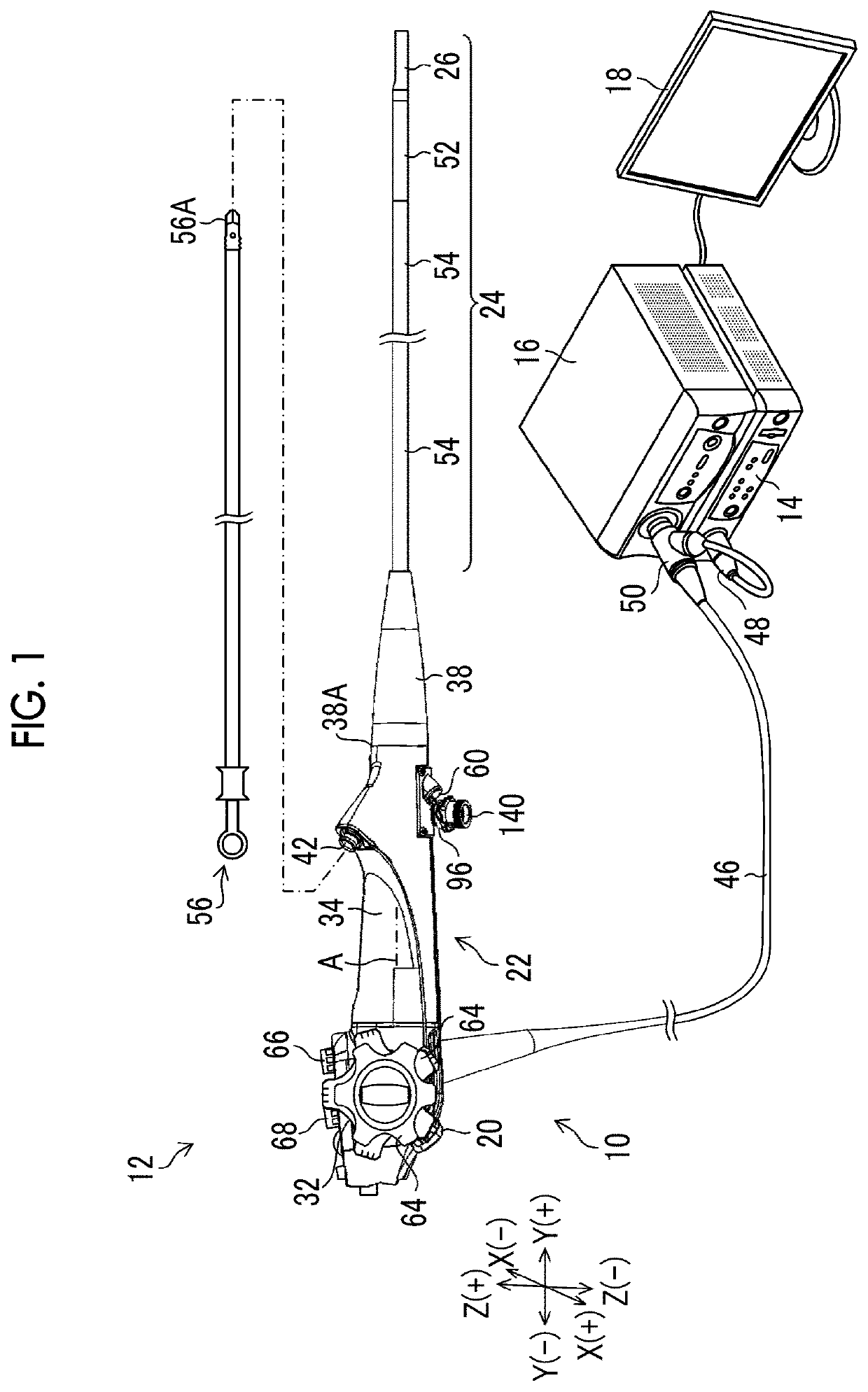
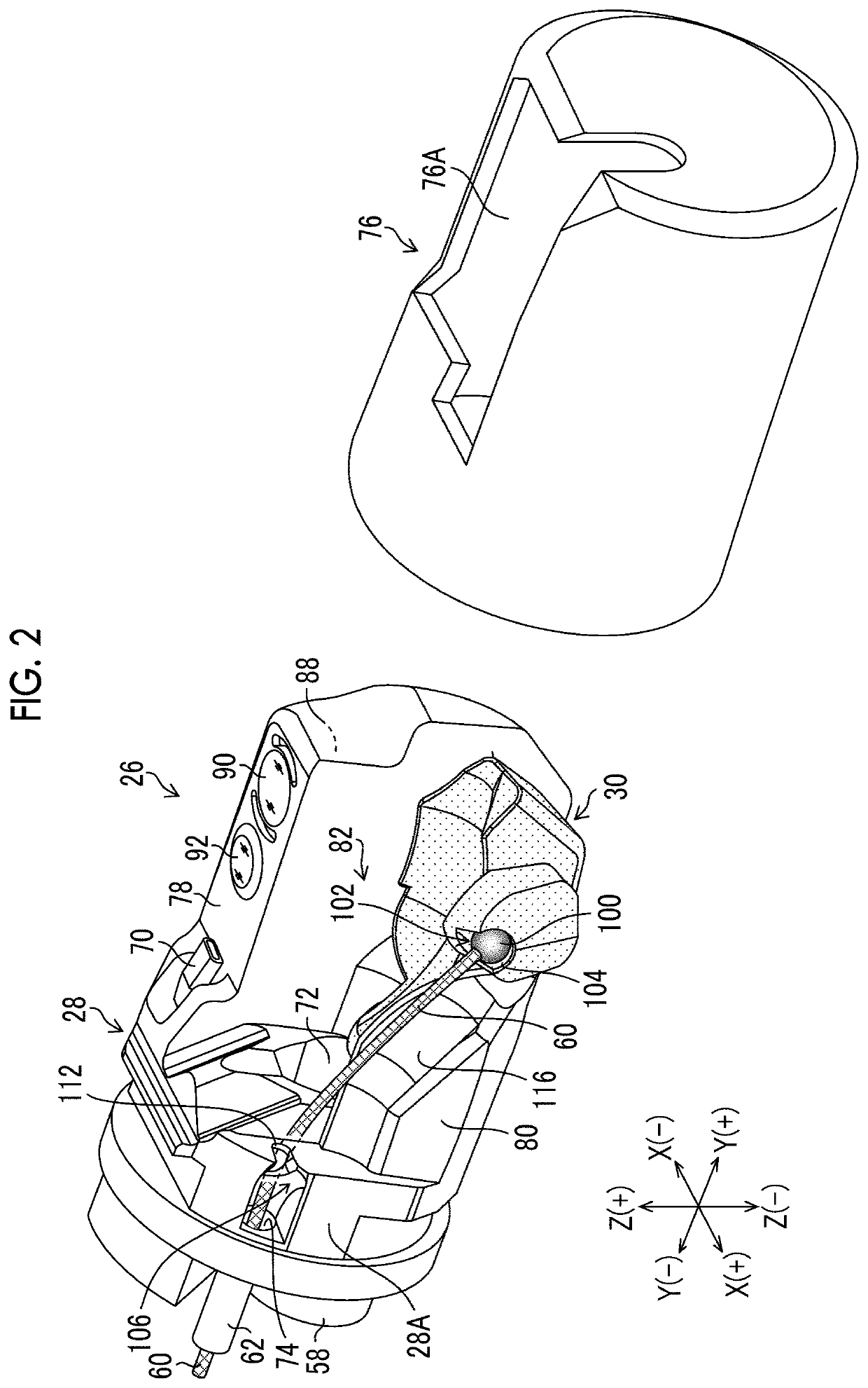
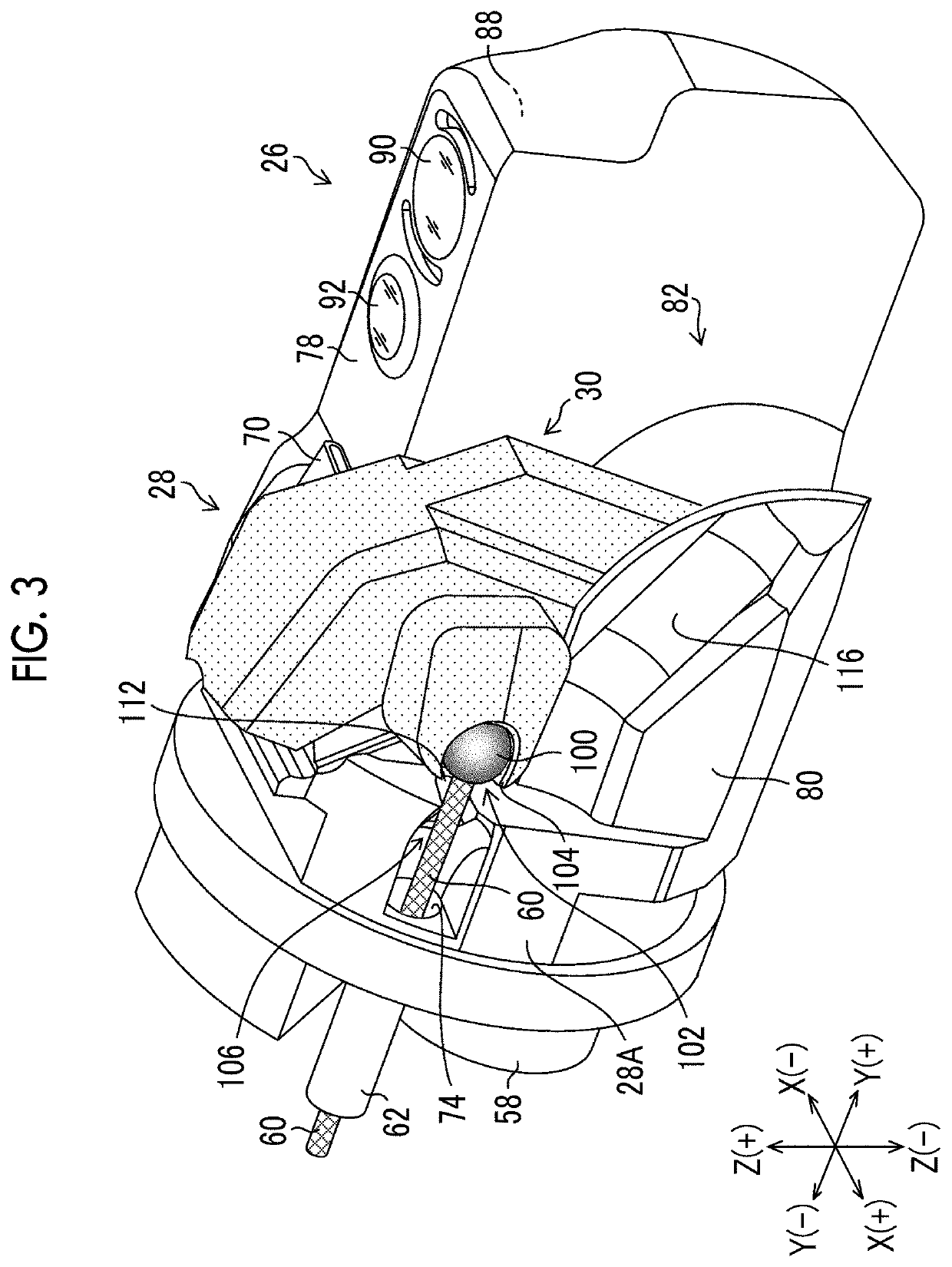
Provided is an endoscope that can easily perform the attachment and detachment work of a proximal end side of a wire without impairing the operability of an operating part.The an endoscope includes an operating part (22) including an erection operating lever (20), an insertion part (24), an elevator (30), a wire (60) that is disposed to be inserted into a wire channel (62) to be movable forward and backward therethrough and is attachably and detachably coupled to the elevator (30) on a distal end side thereof, an opening part (94) that is provided at a proximal end of the wire channel (62) and delivers the proximal end side of the wire (60) to the outside of the operating part (22), a rotating member (96) that is disposed to be exposed to the outside of the operating part (22) and is configured to be rotatable around a rotational axis (96A) having a component in a direction orthogonal to a longitudinal direction of the operating part (22) depending on the operation of the erection operating lever (20), an engaged part (144) that is provided in the rotating member (96), and an engaging part (98) that is provided on the proximal end side of the wire (60) and is engageably and disengageably engageable with the engaged part (144).

Description

CROSS-REFERENCE TO RELATED APPLICATIONS[0001]The present application is a Continuation of PCT International Application No. PCT / JP2018 / 035325 filed on Sep. 25, 2018 claiming priority under 35 U.S.C § 119(a) to Japanese Patent Application No. 2017-188594 filed on Sep. 28, 2017. Each of the above applications is hereby expressly incorporated by reference, in its entirety, into the present application.BACKGROUND OF THE INVENTION1. Field of the Invention[0002]The present invention relates to an endoscope, and particularly, to an endoscope including a forceps elevator that changes a delivery direction of a treatment tool to a distal end part of an insertion part.2. Description of the Related Art[0003]In endoscopes, various treatment tools are introduced from a treatment tool introduction port provided in a proximal operating part (hereinafter referred to as an “operating part”), and the treatment tools are delivered from a treatment tool delivery port opening to a distal end member of an...

Claims


Application Information

Patent Timeline
IPC IPC(8): A61B1/00A61B1/005
CPCA61B1/0055A61B1/0057A61B1/00002A61B1/00066A61B1/00087A61B1/00147A61B1/00137A61B1/00101A61B1/00098A61B1/018G02B23/24
Inventor HARADA, TAKASHI
Owner FUJIFILM CORP
Learn More