Battery pack and vehicle for mounting the same

Active Publication Date: 2020-07-16
TOYOTA JIDOSHA KK
View PDF0 Cites 7 Cited by
  • Summary
  • Abstract
  • Description
  • Claims
  • Application Information

AI Technical Summary

Benefits of technology

[0027]The vehicle according to the present disclosure includes a battery pack mounted under a floor of a vehicle and a elastic member sandwiched between a lower surface of the floor and the battery pack. The battery pack includes a lower case on which a battery stack is placed and that is fixed under the floor, an upper case attached to the lower case and on which the elastic member is placed, and a support member extending upwardly from a rigid body consisting of the battery stack and the lower case and supporting the back surface of the upper case. Any configuration of the battery pack according to the present disclosure may be applied to the battery pack of the vehicle according to the present disclosure. According to this configuration, it is possible to suppress vibrations of the upper case by sandwiching the upper

Problems solved by technology

However, this prior art has problems to be solved.
One of the problems to be solved is to suppress the upper case of the battery pack from vibrating.
Howe

Method used


Image

  • Battery pack and vehicle for mounting the same
  • Battery pack and vehicle for mounting the same
  • Battery pack and vehicle for mounting the same

Examples


Embodiment Construction

[0091]The following is a table of contents showing the contents and the order of description in the embodiment of the present disclosure.

Table of Contents

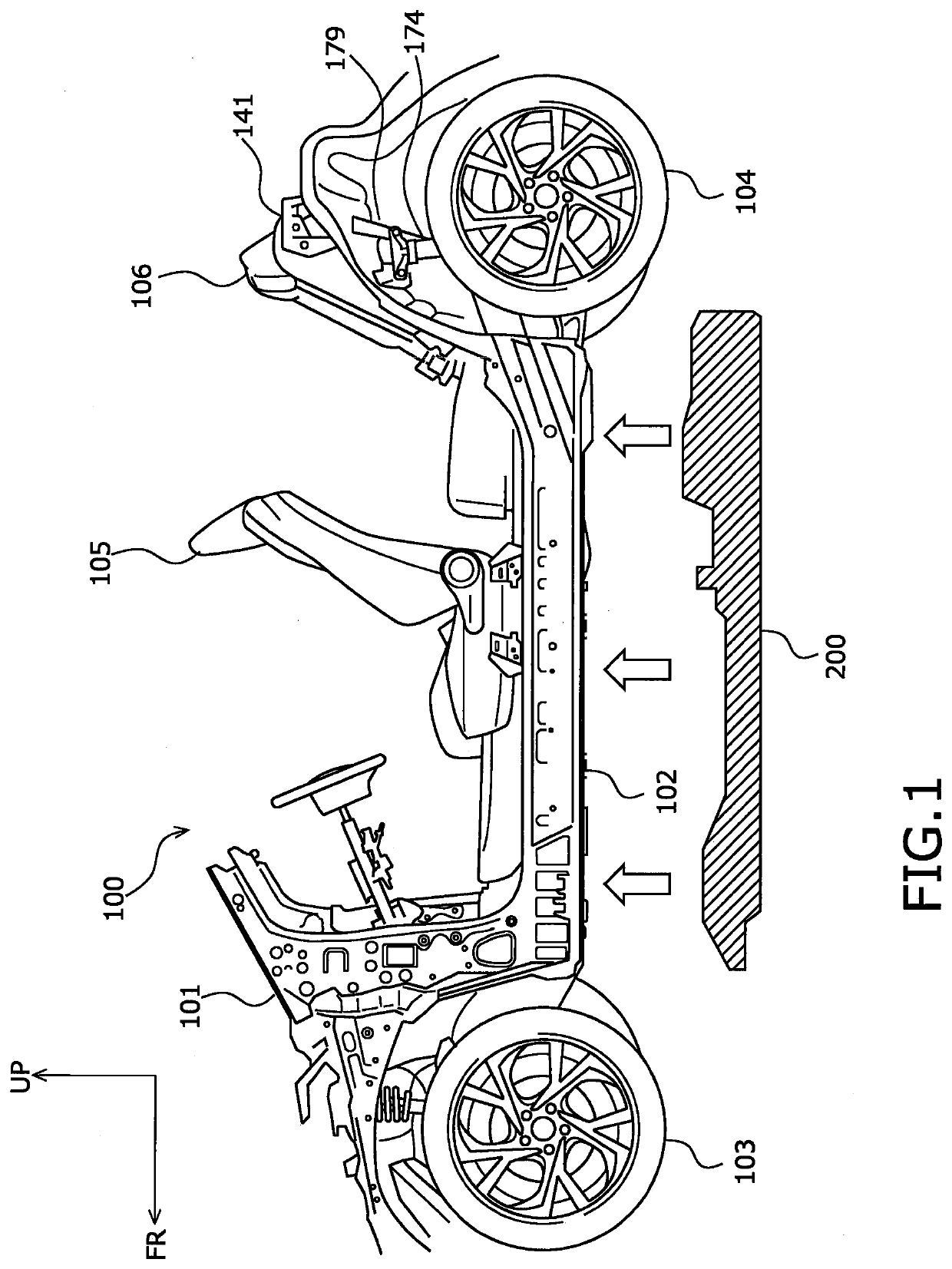
[0092]1. Overview of vehicle[0093]2. Battery pack

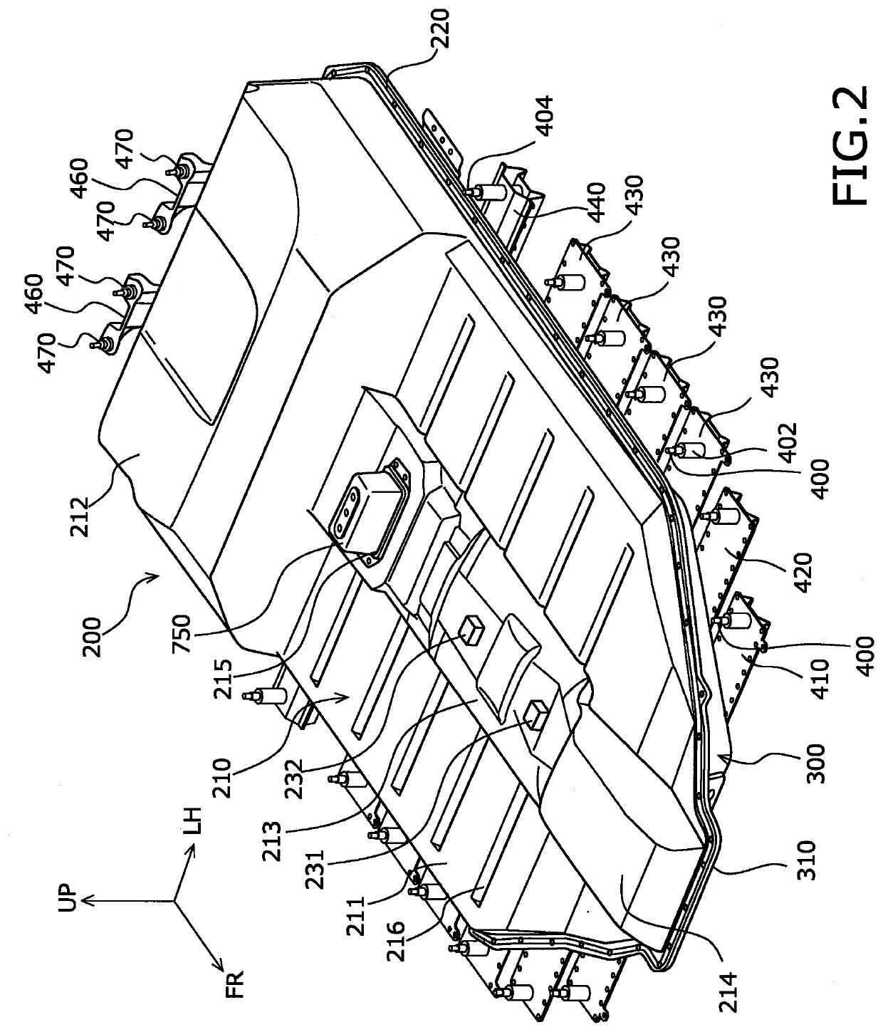
[0094]2-1. Appearance and overview of battery pack

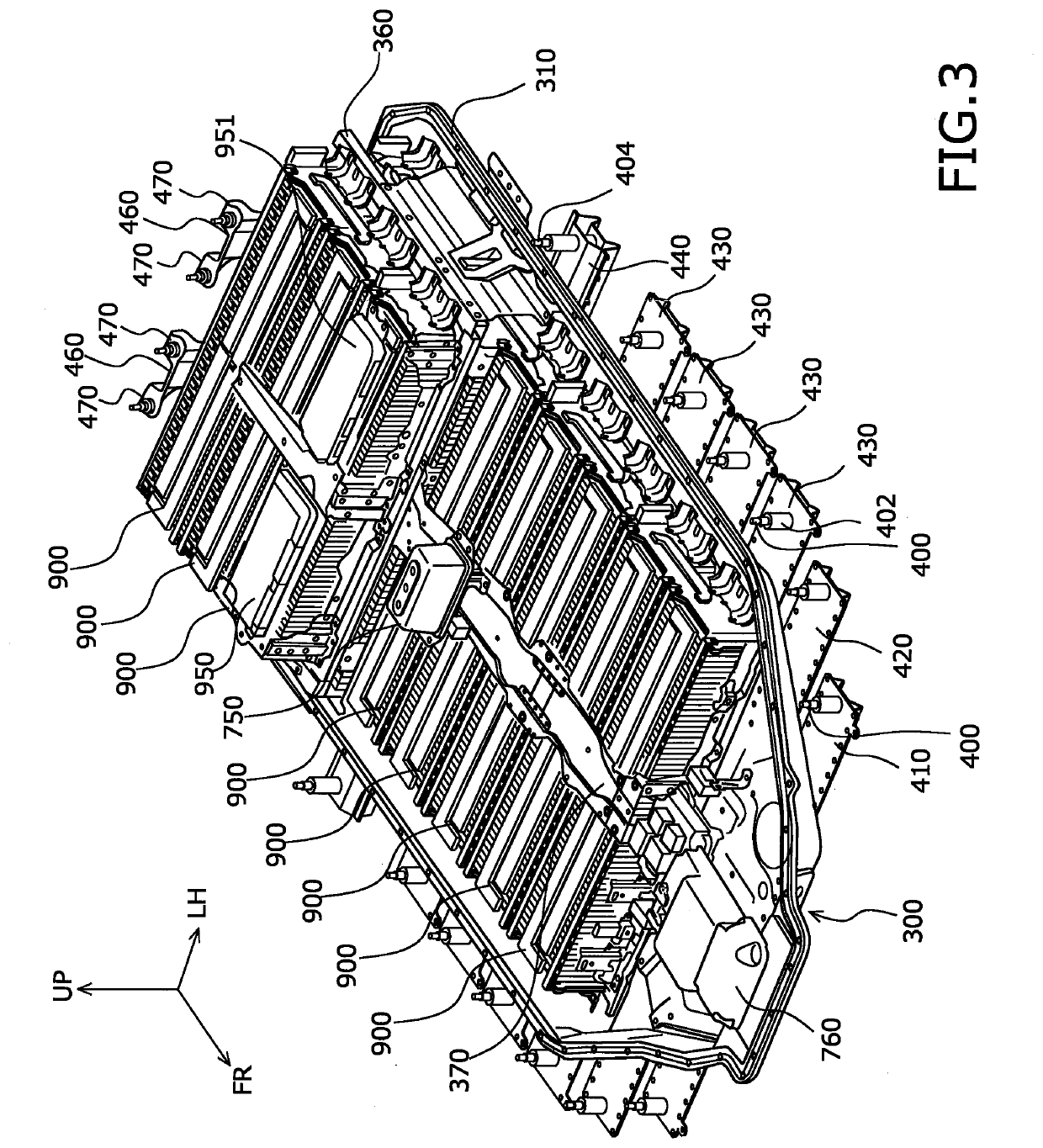
[0095]2-2. Detail of reinforcement structure of lower case

[0096]2-3. Structure of middle frame

[0097]2-4. Detail of middle frame supporting structure

[0098]2-5. Detail of junction structure between reinforcements

[0099]2-6. Detail of frame structure of second floor

[0100]2-7. Detail of lower case rear end

[0101]2-8. Heating / cooling device

[0102]2-9. Cable laying structure

[0103]2-10. Battery stack fixing structure[0104]3. Body structure

[0105]3-1. Overview of body structure

[0106]3-2. Body frame structure

[0107]3-3. Mounting structure of battery pack under floor

[0108]3-4. Mounting structure of battery pack rear end

[0109]3-5. Upper case supporting structure[0110]4. Features and advantages

[0111]4-1. Support of upper case from below by support leg...


PUM


Abstract

The battery pack according to the present disclosure is a battery pack mounted under a floor of a vehicle. The battery pack comprises a lower case fixed under the floor and on which a battery stack is placed, an upper case attached to the lower case, and a support member extending upwardly from a rigid body provided inside the lower case to support a back surface of the upper case. The battery pack may further comprise an elastic member disposed on a surface of the upper case and sandwiched between the upper case and a lower surface of the floor. In such a configuration, it is possible to suppress the upper case of the battery pack from vibrating.

Description

CROSS-REFERENCE TO RELATED APPLICATION[0001]This application is based on and claims the benefit of Japanese Patent Application No. 2019-003737, filed on Jan. 11, 2019 and Japanese Patent Application No. 2019-110589, filed on Jun. 13, 2019, which are incorporated by reference herein in their entirety.BACKGROUNDField[0002]The present disclosure relates to a battery pack and a vehicle for mounting the same.Background Art[0003]U.S. Pat. No. 8,833,499 discloses a prior art battery pack for an electric vehicle and vehicle for mounting the same. However, this prior art has problems to be solved.SUMMARY[0004]One of the problems to be solved is to suppress the upper case of the battery pack from vibrating. In the above-mentioned prior art, an insulating layer for sound insulation, heat insulation, and vibration damping is provided between the lower surface of a body floor and the upper case of the battery pack.[0005]However, it is difficult to say that the upper case of the battery pack can ...

Claims


Application Information

Patent Timeline
IPC IPC(8): H01M2/10B60K1/04B60L50/64
CPCH01M2/1083H01M2/1077B60K1/04H01M2220/20B60K2001/0438B60Y2306/01B60K2001/0472Y02E60/10H01M50/249B60L50/64H01M50/264H01M50/298Y02T10/70
Inventor KUNO, ATSUNORI
Owner TOYOTA JIDOSHA KK
Why Eureka
Try Eureka