Bone clip with resilient arm for proximal compression

a resilient arm and bone clip technology, applied in the field of bone clips, can solve the problems of design not uniformly applying compression along fractures, and achieve the effect of stabilizing bone and more balanced proximal and distal compression

Active Publication Date: 2020-07-23
ACUMED
View PDF3 Cites 5 Cited by
  • Summary
  • Abstract
  • Description
  • Claims
  • Application Information

AI Technical Summary

Benefits of technology

[0004]The present disclosure provides devices and methods for stabilizing bone. The devices and methods may provide a more balanced proximal and distal compression when stabilizing bone. An exemplary device may comprise a staple member including a bridge connecting a first leg to a second leg. The device also may com

Problems solved by technology

However, this design does not apply co

Method used


Image

  • Bone clip with resilient arm for proximal compression
  • Bone clip with resilient arm for proximal compression
  • Bone clip with resilient arm for proximal compression

Examples


example 1

mber Configurations

[0050]This example describes exemplary alternative spring member configurations for incorporation into bone clip 50 of FIGS. 3, 3A, and 4-9; see FIGS. 10-14. Only one leg 56 and an end region of bridge 54 are shown for each embodiment. Each other leg 56 of the clip may (or may not) be associated with a spring member, optionally similar to what is shown.

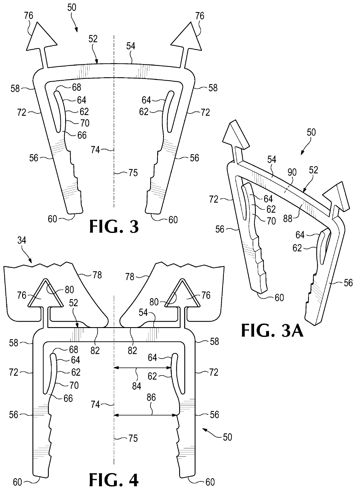
[0051]FIG. 10 shows a bone clip 50 having a spring member 62 in the form of a resilient arm 64 projecting distally from bridge 54. A fixed end 66 of arm 64 is located at the junction between bridge 54 and leg 56, and a free end 68 of the arm is located distally therefrom, closer to lower end 60 of leg 56.

[0052]FIG. 11 shows a bone clip 50 having a spring member 62 with no free end.

[0053]Instead, both ends are fixed to staple member 52.

[0054]FIG. 12 shows a bone clip 50 having a spring member 62 formed by a pair of resilient arms 64a, 64b. Each arm 64a, 64b has a fixed end 66 and a free end 68. Arm 64a projects dista...

example 2

s with at Least Three Legs

[0057]This example describes exemplary bone clips 50 having at least three legs and including a spring member and / or resilient arm to apply proximal compression to bone; see FIGS. 15-17.

[0058]FIG. 15 shows a bone clip 50 having four coplanar legs 56 each associated with a respective resilient arm 64. In other embodiments, only a subset of legs 56 are associated with a resilient arm 64.

[0059]FIG. 16 shows a bone clip 50 having a triangular arrangement of three legs 56 each associated with a resilient arm 64. In other embodiments, only a subset of legs 56 are associated with a resilient arm 64.

[0060]FIG. 17 shows a bone clip 50 having a rectangular arrangement of four legs 56 each associated with a resilient arm 64. In other embodiments, only a subset of legs 56 are associated with a resilient arm 64.

example 3

with Pivotally Connected Members

[0061]This example describes an exemplary bone clip 120 including at least one pivotally connected elongate member 122; see FIG. 18.

[0062]Bone clip 120 includes a staple member 52 having a bridge 54 connecting a pair of legs 56 to one another. Bridge 54 and a pair of upper leg regions 124 are formed by a body 126, which may be only one piece. A respective elongate member 122 is pivotally connected at a pivotable joint 128 to a distal end of each upper leg region 124. Elongate member 122 forms a lower leg region 130 of one of legs 56 and also forms an arm 132. However, arm 132 may be substantially less deformable than arm 64 of bone clip 50. Arm 132 may be firmly attached to lower leg region 130 (e.g., formed integrally with the lower leg region), and may extend proximally from pivotable joint 128 to a proximal end 134.

[0063]Bone clip 120 may be installed as described above in Section II for bone clip 50. However, pivotal motion of each elongate member...


PUM


Abstract

Devices and methods for stabilizing bone. The devices and methods may provide a more balanced proximal and distal compression when stabilizing bone. An exemplary device may comprise a staple member including a bridge connecting a first leg to a second leg. The device also may comprise a resilient arm elongated between a fixed end and a free end, and projecting from the first leg and/or from an end region of the bridge adjoining the first leg. At least a portion of the resilient arm intermediate the fixed and free ends may be inwardly adjacent and spaced from an upper region of the first leg.

Description

INTRODUCTION[0001]A bone clip, also called a bone staple, is a fastener for stabilizing bone. The clip may be installed in one or more bones to span a discontinuity in the bone(s), such as a fracture, a cut, or an anatomical joint. Once installed, the clip applies compression across the discontinuity, to encourage healing and / or fusion.[0002]An exemplary bone clip 20 representing the prior art is shown in FIGS. 1 and 2, respectively during and after insertion into a bone 22. The bone has a fracture 24 that creates bone fragments 26, 28. Clip 20 has a pair of serrated legs 30 connected to one another with a bridge 32. Legs 30 extend along convergent paths from bridge 32 when clip 20 is in an undeformed, relaxed configuration (not shown). Clip 20 is composed of an elastically deformable material, which allows the clip to be placed and held temporarily in a stressed configuration with an insertion tool 34. For example, tool 34 may have upper and lower jaws 36, 38 that apply a bending m...

Claims


Application Information

Patent Timeline
IPC IPC(8): A61B17/064A61B17/068
CPCA61B2017/0641A61B17/10A61B17/8004A61B17/0682A61B2017/0645A61B2017/00867A61B17/0642
Inventor SEYKORA, ANDREW W.SUCEC, MATTHEW C.WEDAM, BRANDON
Owner ACUMED
Why Eureka
Try Eureka